
08 Altima vq35 into 2003 maxima


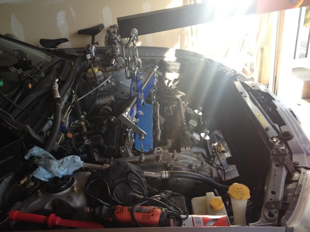
Today I got the engine installed in the bay. I had to do a few things to make it all work.
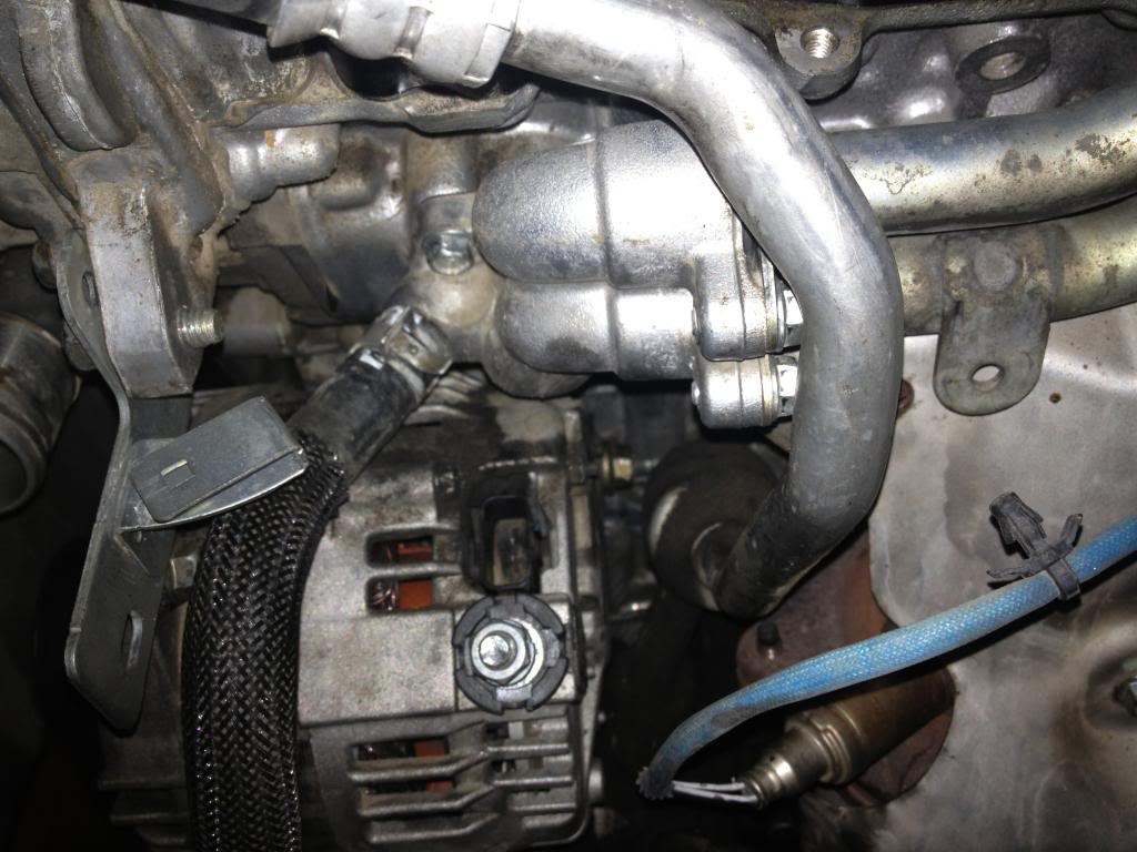
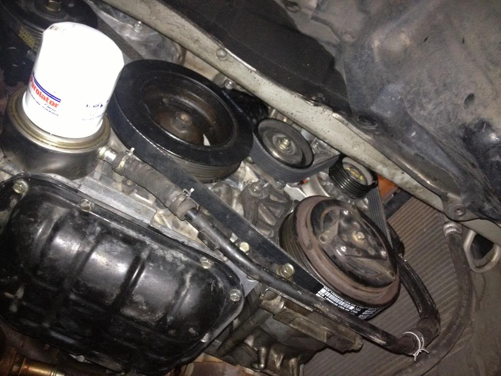
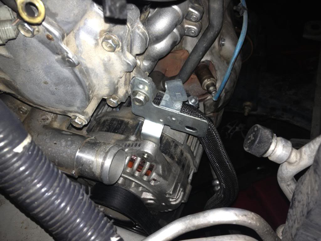
I fabricated a mounting point for the alternator using parts off of the 08 engine, it didn't come with the 08 alternator mounting bracket for whatever reason. Either that or I lost it in the process.
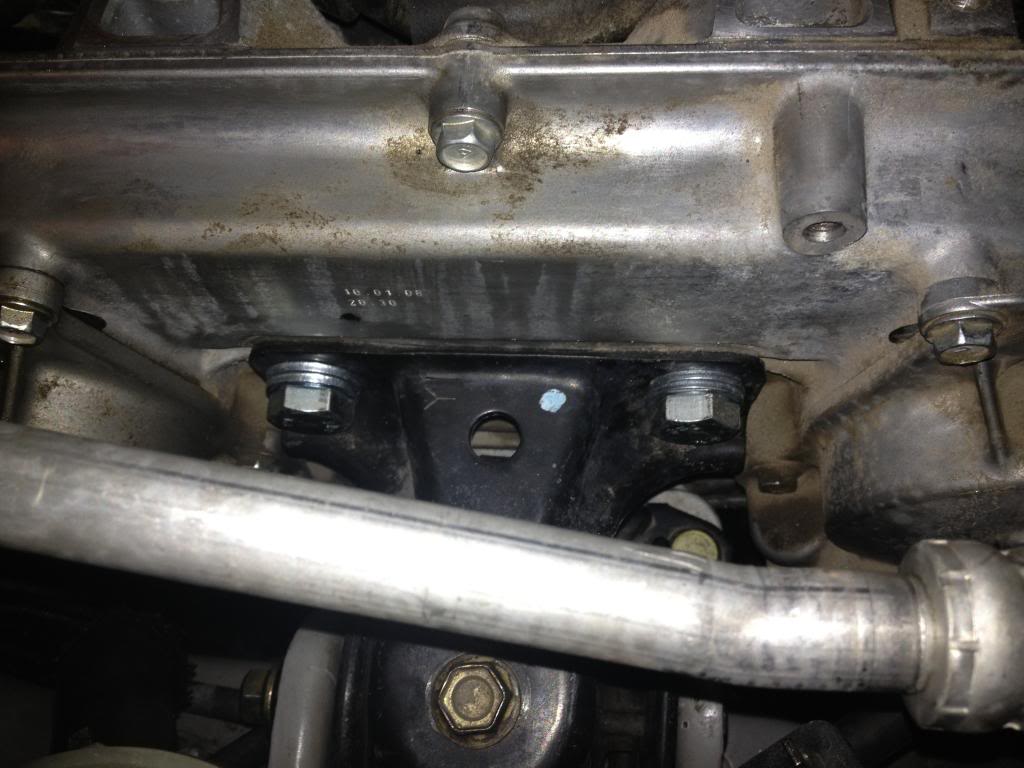
Just like suratt's build, I had to bore out the holes for the upper passenger side mount and get new bolts. Worked just fine otherwise. Also, the adjuster has the washers on it to space it out, ended up having to use quite a few and it was a tight fit for the belt, especially since it's a brand new belt. It looks like I might have to pull off the bracket again to fit the connector to the VTC solenoid on bank 2. It's a tight fit.
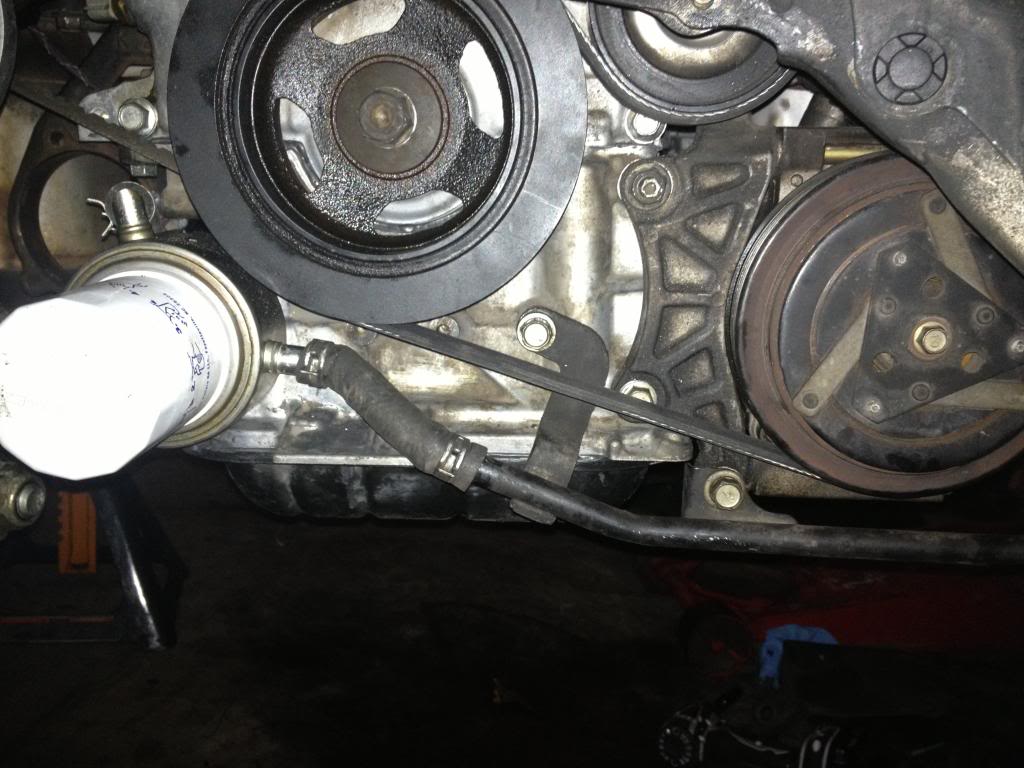
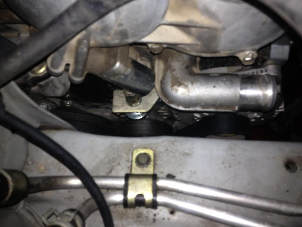
The oil cooler I was able to make fit using both the 03 and the 08 cooler lines to make things fit with the 09 fitting coming off the water inlet tube. Seems like it fits perfect! I will know more when the radiator is in.
Pictures from today.
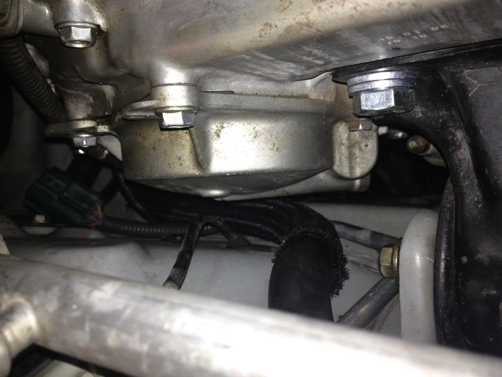
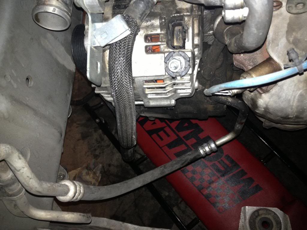
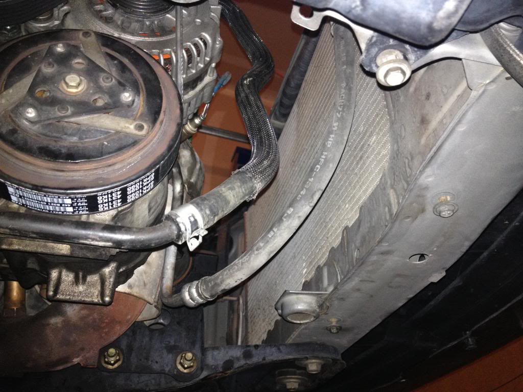
This one looks like I might have to cut a longer piece of hose to fit better. Will probably do tomorrow.

I fabricated a mounting point for the alternator using parts off of the 08 engine, it didn't come with the 08 alternator mounting bracket for whatever reason. Either that or I lost it in the process.
Just like suratt's build, I had to bore out the holes for the upper passenger side mount and get new bolts. Worked just fine otherwise. Also, the adjuster has the washers on it to space it out, ended up having to use quite a few and it was a tight fit for the belt, especially since it's a brand new belt. It looks like I might have to pull off the bracket again to fit the connector to the VTC solenoid on bank 2. It's a tight fit.
The oil cooler I was able to make fit using both the 03 and the 08 cooler lines to make things fit with the 09 fitting coming off the water inlet tube. Seems like it fits perfect! I will know more when the radiator is in.
Pictures from today.
This one looks like I might have to cut a longer piece of hose to fit better. Will probably do tomorrow.
Last edited by q.man06; Mar 13, 2013 at 09:13 PM.
I got the transmission in today! It took some finess but I finally got her in.
When I went to put up the flywheel I noticed that it seemed a tight fit, so as I was pulling it off I dropped it on my hand. Also, when the flywheel hit the ground it wedged one of the flywheel bolts between the plates and ruined it. Me being dumb I thought it was good enough to be OK and I threaded it back in. Well, it didn't go in all the way.
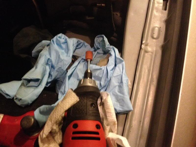
SO at work I have a few machine shop items available to me, and with the help of a co-worker we came up with a homemade thread tap.
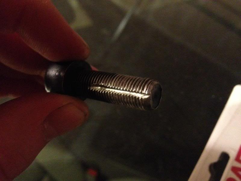
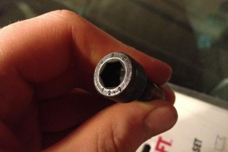
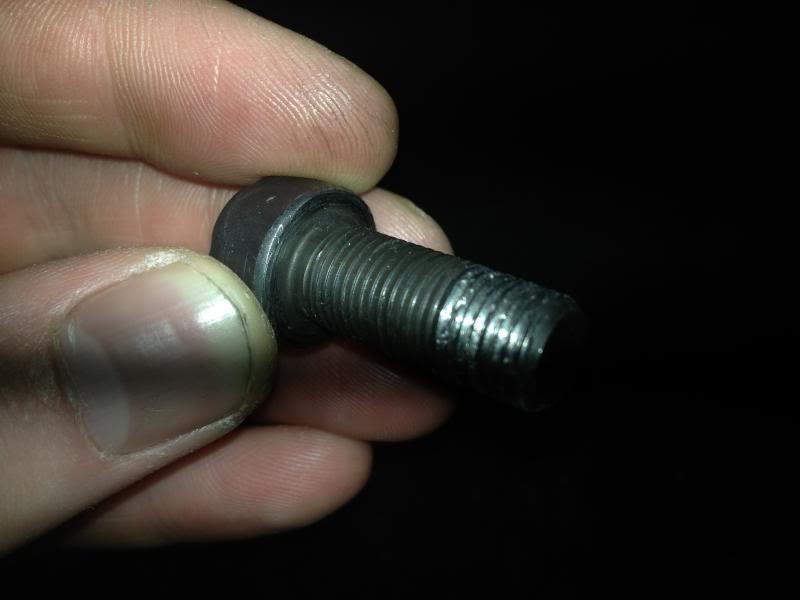
Skeptical that it would work, I tried it anyways, and it worked beautiful. We then modified a bolt like the one above and made it work for a flywheel bolt. It's actually nicer than the factory bolts honestly, and at 50 cents a piece, totally worth it!
Pic of the trans in. I should be able to get more done on it this weekend since i'm not working. Will keep updates coming.

When I went to put up the flywheel I noticed that it seemed a tight fit, so as I was pulling it off I dropped it on my hand. Also, when the flywheel hit the ground it wedged one of the flywheel bolts between the plates and ruined it. Me being dumb I thought it was good enough to be OK and I threaded it back in. Well, it didn't go in all the way.
SO at work I have a few machine shop items available to me, and with the help of a co-worker we came up with a homemade thread tap.
Skeptical that it would work, I tried it anyways, and it worked beautiful. We then modified a bolt like the one above and made it work for a flywheel bolt. It's actually nicer than the factory bolts honestly, and at 50 cents a piece, totally worth it!
Pic of the trans in. I should be able to get more done on it this weekend since i'm not working. Will keep updates coming.
Last edited by q.man06; Mar 15, 2013 at 09:47 PM.


i would measure the weight of a standard oem flywheel bolt and the one you used as a replacement
if the difference is too big - i would not use it, because of moved balance
of course your flywheel wouldn't start vibrating the next day, but is you plan to use it for another 200k - better to go with oem
if the difference is too big - i would not use it, because of moved balance
of course your flywheel wouldn't start vibrating the next day, but is you plan to use it for another 200k - better to go with oem
The bolt is stronger than a grade 8 I was told. That's what the fastener shop told me, and that's all they deal with is fasteners so I trust that. It torqued down just fine with all of the others.
Right now i'm getting the wiring all sorted out between the 03 and altima 08 FSM's. I think I finally got it figured out-- Now just to wire it up!
I figure the weight difference would be minimal. It's exactly the same dimensions as the stock ones. There are 8 of them and I can't imagine just one would make that much of a difference. I guess we'll see
The bolt is stronger than a grade 8 I was told. That's what the fastener shop told me, and that's all they deal with is fasteners so I trust that. It torqued down just fine with all of the others.
Right now i'm getting the wiring all sorted out between the 03 and altima 08 FSM's. I think I finally got it figured out-- Now just to wire it up!

nice progress going, do you plan on getting o2 eliminators/sims or there is no need for your state?
Last edited by shaks; Mar 18, 2013 at 10:08 AM.


I will make a wiring diagram for that one also but there is a how-to on the forums.
Tunermaxima3000,
Thanks man, I'm excited to get this thing going! It's so close.


hey man,
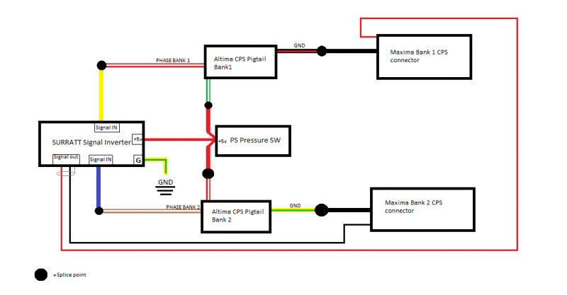
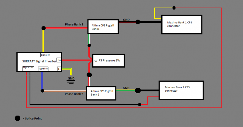
looking at the cam signal inverter wiring diagram trying to figure it out. I'm not sure if its correct.
I'm confused at the ECU, the 2 wires going strait to the cam pos connectors.
The ecu cam sensor wires should be going to the OUT wires on the signal inverter. (the grey shielded wires red and black).
hey man,
looking at the cam signal inverter wiring diagram trying to figure it out. I'm not sure if its correct.
I'm confused at the ECU, the 2 wires going strait to the cam pos connectors.
The ecu cam sensor wires should be going to the OUT wires on the signal inverter. (the grey shielded wires red and black).
The two black wires connecting the ECU to the CMP connectors are just showing the cable between the connector and the ECU. I should have made that more specific.
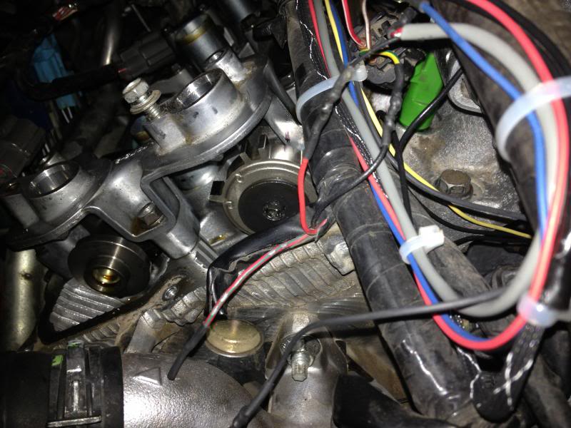
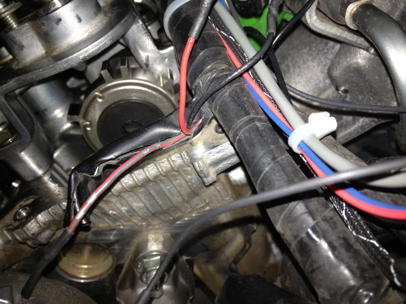
The bank 1 and bank 2 Cam position sensor connectors are the female ends that head back to the ECU. The black and red wires coming off the inverter that are circled with the shielding showing it's terminated in the signal inverter (I assume at least, your instructions didn't mention terminating the shield to anything). I think I might go back through and label all of the wires for their respective signal and repost-- maybe tomorrow.
CMP pigtail pinout per 2008 Altima FSM
Terminal No. - Wire Color - Signal Name
BANK 1 CPS
1 - GRN/WHT - AVCC1
2 - BLK/RED - GND
3 - WHT/RED - PHASE
BANK 2 CPS
1 - RED/WHT - AVCC1
2 - YEL/GRN - GND
3 - BRN/WHY - PHASE
CPS pinout per 2003 Maxima FSM
BANK 1 CPS
1 - BLK - GND
2 - YEL - PHASE
BANK 2 CPS
1 - BLK - GND
2 - RED - PHASE
Pin 3 of Maxima is left out due to +12v power source.
Last edited by q.man06; Mar 18, 2013 at 08:16 PM.


Nice work....grrrr, but you're tempting me. Spring is almost here and I'm getting a heavy right foot..this thing better not dyno at 280whp...lol...but I totally hope for you that it does 
Btw, that bolt you used for your flywheel is a 12.9 so roughly 50% stronger than a grade 8, but less resistant to overtorquing.
Keep up the good work, and thanks for sharing the wiring diagrams-looking forward to your "It's up and running" post.
Btw, that bolt you used for your flywheel is a 12.9 so roughly 50% stronger than a grade 8, but less resistant to overtorquing.
Keep up the good work, and thanks for sharing the wiring diagrams-looking forward to your "It's up and running" post.
Nice work....grrrr, but you're tempting me. Spring is almost here and I'm getting a heavy right foot..this thing better not dyno at 280whp...lol...but I totally hope for you that it does
Btw, that bolt you used for your flywheel is a 12.9 so roughly 50% stronger than a grade 8, but less resistant to overtorquing.
Keep up the good work, and thanks for sharing the wiring diagrams-looking forward to your "It's up and running" post.
Btw, that bolt you used for your flywheel is a 12.9 so roughly 50% stronger than a grade 8, but less resistant to overtorquing.
Keep up the good work, and thanks for sharing the wiring diagrams-looking forward to your "It's up and running" post.
I thought that's what it's number meant. I just wasn't sure. Thanks for the info!
BTW, IT'S UP AND RUNNING!!!! FIRED UP ON THE FIRST TRY!
I just have to get the wiring redone because it's super ghetto rigged for testing it.
Thanks everyone for your support on this, special thanks to Surratt for the signal inverter and pioneering such a similar swap.
I will try and have pictures up tomorrow showing the finalized wiring tucked and everything else finished up.
Congrats man!!!!!!!!!!!!!!
only 2 pages in and its running!
I remember my swap, wow it was FUN. But those 2 months of it being together and not running was hard at times!
Tonight I got her all wired up and roadworthy. She drives great! My old engine lost that smooth smooth running feel and it's really nice to have that back.
A few issues I'm not sure what to do with yet.
- VIAS valves since there are now two.
- EVAP solenoid, don't care to keep it but need CEL to go away.
And because I haven't moved the signal plates, i'm throwing p0011 and p0021. I'll probably cut the notch and move them tomorrow. It's kinda stumbling when it settles down at idle, it drops to ~400-500 rpm. Not sure if that's because the ECU hasn't adjusted to the new TB yet? I dunno, but i'll figure the current issues out and tackle that one later.
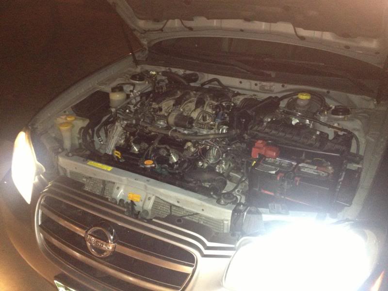
Here's some pictures of it in the car! The fitment of the outer components was OK. The air box doesn't fit exactly where it used to be, although you can still get a bolt or two in there. Upper radiator hose interferes with a protrusion from the front valve cover, but a quick cut fixed that. It really went together well overall!

So... since this is out of a 4th gen altima, does that make me the first 5.4 gen max? I mean, 5.4 sounds lame, maybe we should add it up and make it 5.9 gen... I dunno, thoughts?
A few issues I'm not sure what to do with yet.
- VIAS valves since there are now two.
- EVAP solenoid, don't care to keep it but need CEL to go away.
And because I haven't moved the signal plates, i'm throwing p0011 and p0021. I'll probably cut the notch and move them tomorrow. It's kinda stumbling when it settles down at idle, it drops to ~400-500 rpm. Not sure if that's because the ECU hasn't adjusted to the new TB yet? I dunno, but i'll figure the current issues out and tackle that one later.
Here's some pictures of it in the car! The fitment of the outer components was OK. The air box doesn't fit exactly where it used to be, although you can still get a bolt or two in there. Upper radiator hose interferes with a protrusion from the front valve cover, but a quick cut fixed that. It really went together well overall!
So... since this is out of a 4th gen altima, does that make me the first 5.4 gen max? I mean, 5.4 sounds lame, maybe we should add it up and make it 5.9 gen... I dunno, thoughts?
Last edited by q.man06; Mar 20, 2013 at 10:25 PM.


1st off congrats on your build..... I cant believe you got it up and running so fast!
The 1st and 2nd gen Altimas didn't have VQs so they don't count. Your Maxima is a 5.5 so I would name it 5.6. or 5.75.
To put it another way: which year/gen Maxima has the Vq35 closest to that altima vq35? I would then go from there.
The 1st and 2nd gen Altimas didn't have VQs so they don't count. Your Maxima is a 5.5 so I would name it 5.6. or 5.75.
To put it another way: which year/gen Maxima has the Vq35 closest to that altima vq35? I would then go from there.

Member
Joined: Nov 2006
Posts: 128
I agree, and you can also delete the canister and lines. Also, which DTC are you pulling relating to "EVAP"? 444 and 445 relate to the solenoid that is up front. 447 relates to the valve and canister that is at the gas tank.

I don't want to delete the VIAS due to the torque decrease on the low end, Just want to get it back up and functioning. I might just T off the output line to accommodate both valves, we'll see how that works. Curious to see if it would work better keeping the vacuum tank or not. The altima engine came with two VIAS valves, I think it would be easier to just slap a T fitting in over wiring that mess up.
SurraTT do you have some input on this from yours? I'll have to go through your thread and look.
The codes i'm throwing for the VIAS is p1800, so I need to check to make sure it stayed plugged in.
SurraTT do you have some input on this from yours? I'll have to go through your thread and look.
The codes i'm throwing for the VIAS is p1800, so I need to check to make sure it stayed plugged in.
you need to keep the EVAP stuff. ITs easy to hook that up. use the lil port near the TB. it works fine.
VIAS keep the valves. i used a T connector like you said and run both with 1 vias solenoid.
I DID gut my old i/m and test bop, but i recently picked up a stock i/m with working vias that i will be using.
Also. Call it a 5.7 gen.
the name 5.7 gen can account for any HR headed vq swap. 5.7 gen swap to me means HR FWD VQ motor.
So far so good guys! I've got a few miles on her and no codes! Might still have a small vacuum leak but the car seems to run better the more I drive it.
I will be putting up more documentation tonight regarding the wiring and the cam sensor signal plate modification.
I will be putting up more documentation tonight regarding the wiring and the cam sensor signal plate modification.
Last edited by q.man06; Mar 22, 2013 at 06:23 PM.
Here are the wiring diagrams I promised, along with a few photos. It's been snowing like crazy here so I haven't had the time to update like normal. It's been about 100 miles since I moved the signal plates and NO CODES!
The only thing I had to do, was the idle relearn procedure found here on the website. Link --> http://forums.maxima.org/5th-generat...a-02-03-a.html
The idle was dipping down to ~400-500 rpm before I did the relearn, but now it seems perfect!
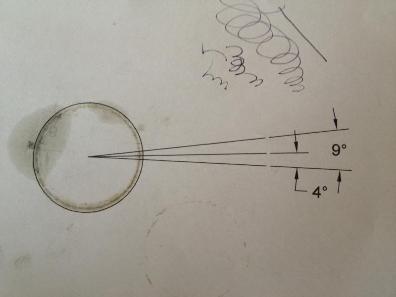
To move the signal plates, I used a sharpie (accurate, I know) and a CAD drawing that I printed to fit the signal plate diameter. The picture is of the used drawing, I can upload the actual CAD document if anyone would like it.
Revised Signal Inverter wiring:
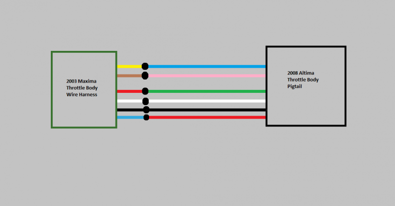
Throttle actuator wiring:
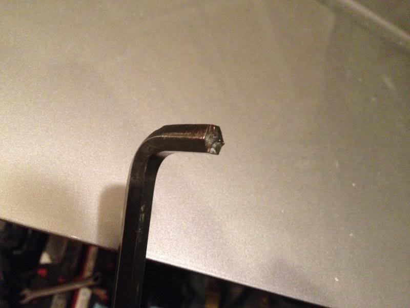
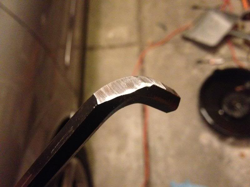
I had to modify an 8mm allen wrench to get at the signal plate. I cut about 1/2 inch off the end, and grinded down the angular part.

To cut off the tabs on the signal plates, I just used a grinding wheel on a dremel tool. Took them off super easy!
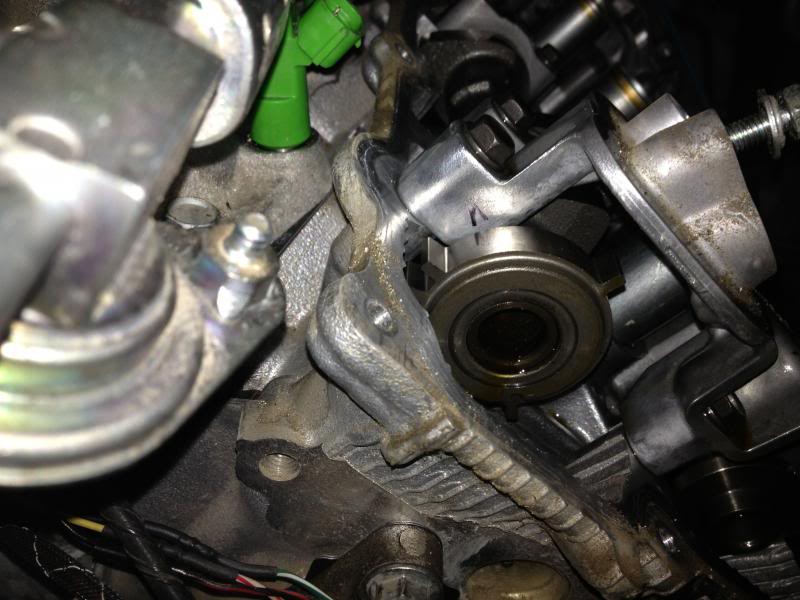
Sharpie mark on bank 2
Sharpie mark on bank 1
One mistake I made on the VIAS-- I didn't look at the vacuum hose routing from when I pulled it off, so I accidenally swapped them on the solenoid ports. Made a nice whistle!
I reconnected it properly and it feels much better! Once I detail the car (hopefully this week sometime) I will post back more pictures
Also, I can't seem to get the snorkel to fit properly, I might have to do some cutting to get it mounted back up. With the throttle body more towards the front of the bay, it doesn't let everything fit as I'd like.
The only thing I had to do, was the idle relearn procedure found here on the website. Link --> http://forums.maxima.org/5th-generat...a-02-03-a.html
The idle was dipping down to ~400-500 rpm before I did the relearn, but now it seems perfect!
To move the signal plates, I used a sharpie (accurate, I know) and a CAD drawing that I printed to fit the signal plate diameter. The picture is of the used drawing, I can upload the actual CAD document if anyone would like it.
Revised Signal Inverter wiring:
Throttle actuator wiring:
I had to modify an 8mm allen wrench to get at the signal plate. I cut about 1/2 inch off the end, and grinded down the angular part.
To cut off the tabs on the signal plates, I just used a grinding wheel on a dremel tool. Took them off super easy!
Sharpie mark on bank 2
Sharpie mark on bank 1
One mistake I made on the VIAS-- I didn't look at the vacuum hose routing from when I pulled it off, so I accidenally swapped them on the solenoid ports. Made a nice whistle!
I reconnected it properly and it feels much better! Once I detail the car (hopefully this week sometime) I will post back more pictures
Also, I can't seem to get the snorkel to fit properly, I might have to do some cutting to get it mounted back up. With the throttle body more towards the front of the bay, it doesn't let everything fit as I'd like.
Last edited by q.man06; Mar 24, 2013 at 05:47 PM.
Brief update on the 5.7 gen
3k code less miles. Runs damn near perfect.
One note to others doing this swap-- make sure you do a full ecu reset. This made the engine run exponentially better.
There will be a Dyno, hopefully sooner rather than later. Will update again with numbers and Dyno graph. The big deal is to see what the AFR's are going to look like.
I figure some will want to know about this--
Just a quick update, this engine swap passed emissions without any trouble at all. It was actually better than it's ever been. This is on the factory 03 ECU, everything pretty much stock.
Colorado Emissions
OH, and I've got 16k miles since the swap. Zero problems. I have the cam plates close enough that it doesn't throw codes, but I will verify with Torque Free when I get some time.

Yes; however, i'm trying to get everything worked out with this car. It's 99% right now.
I just got the ability to datalog and look at the timing. It looks like i'm off a few degrees right now, which could cause some power loss. I just advanced the base timing through the computer which helped, but it's putting me at the stock advance actual because of the improperly adjusted signal plates.
Once I get those dialed in, I will go. I will also have to see what the long term fuel trims are looking like then. Right now they are adding between 8-15% fuel for each bank, just want to make sure it's not running TOO lean.

