When you click on links to various merchants on this site and make a purchase, this can result in this site earning a commission. Affiliate programs and affiliations include, but are not limited to, the eBay Partner Network.
How to Install an Alarm/ Remote Start/ Keyless Entry
2000-2001 Maxima Automatic.
This is a thread Im starting for the winter on installation of a Alarm / Keyless entry / Remote start using an Scytek Astra 4000rs with a IDataLink for the ignition bypasss. I am editing the Pictures now so they will be up tonight when I get home.
These are the systems I used if you are interested in DIY. Shop around and you will find them cheaper.
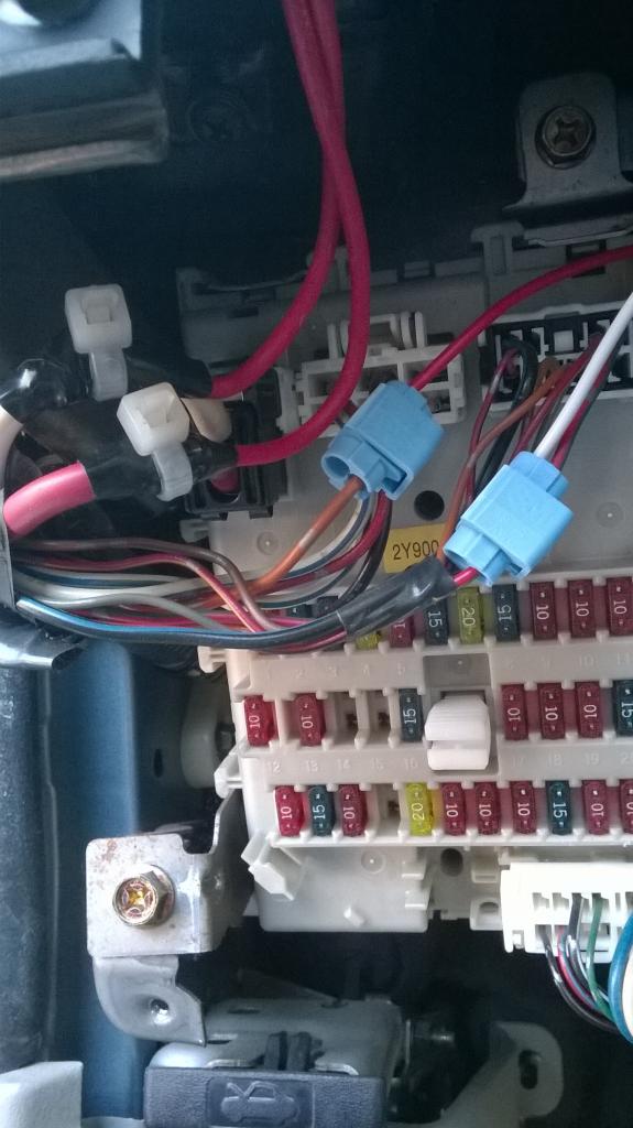
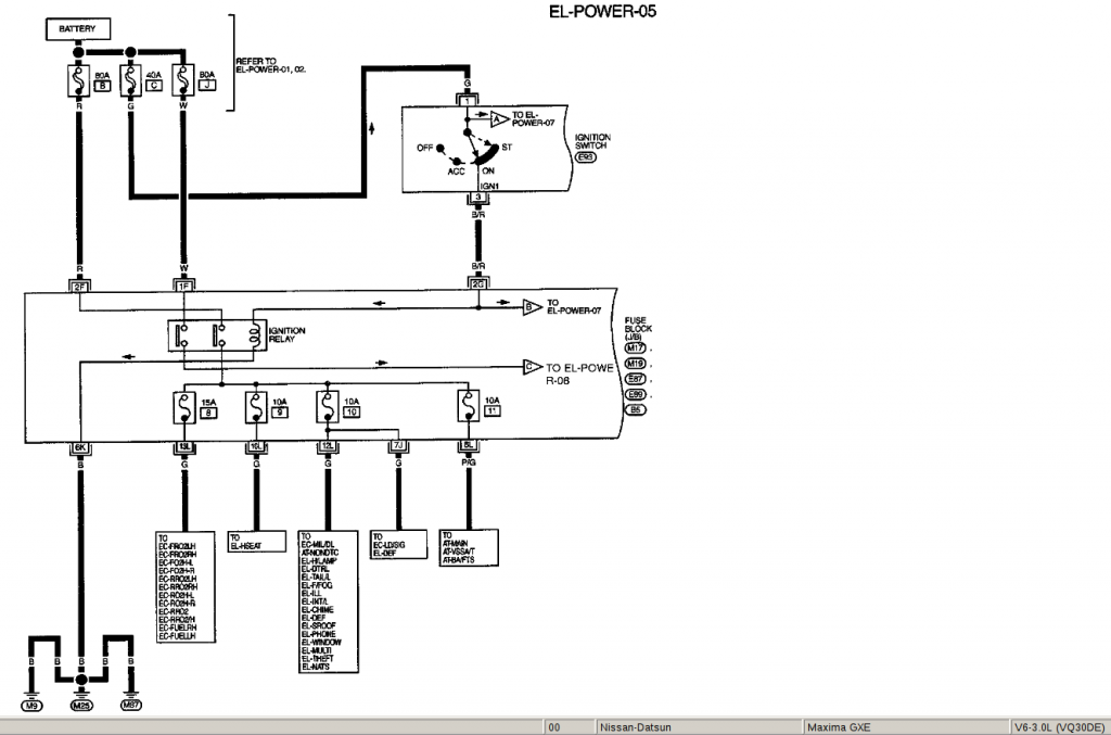
The Two BIG red and one LITTLE red wires are power to the Alarm.
(The location is at the Fuse Box. Left knee)
The Two THICK red wires from the Alarm are connected to the main RED and WHITE wires going into the fuse box.
These are the power wires that send power to the ignition and to the parking lights
The Smaller RED wire is Connected to the BROWN wire as shown on the fuse box to supply basic power to the alarm.
The White Wire Is the parking lights output from the Alarm. In the Astra alarm you have to open the alarm Box and change the jumper to make it +Positive output.
This wire connects to the RED/GREEN STRIPE wire as shown for the parking lights.
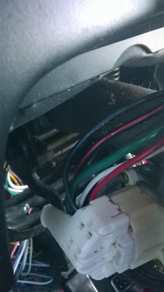
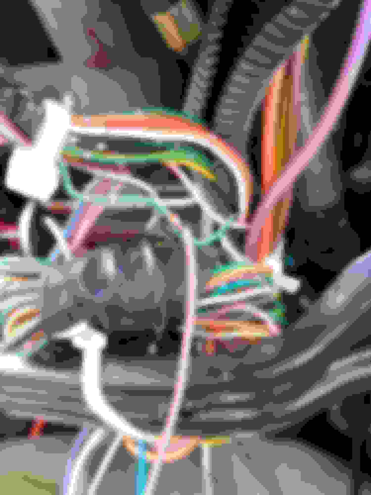
This is of course the LEFT side of the Steering Column.
There's are FOUR Phillips head screws underneath that hold the covers together along with the plastic ring around the key cylinder that just pops off.
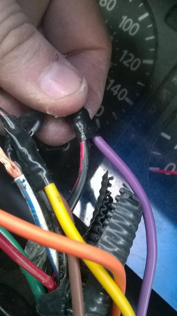
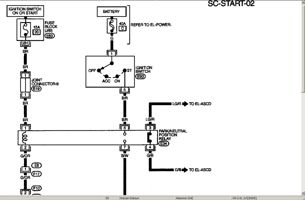
In the Maxima, IT REQUIRES TWO STARTER WIRES TO BE CONNECTED TO START THE LARGE BLACK/RED STRIPE and LARGE BLACK/BLUE STRIPE.
The LARGE PURPLE wire from the alarm goes to the LARGE BLACK/RED STRIPE wire.
The LARGE BROWN wire from the alarm goes to the LARGE BLACK/BLUE STRIPE wire. NOTE..YOU HAVE TO PROGRAM THE BROWN WIRE ON THE ASTRA ALARM TO SECOND START WIRE. IT IS AND ACCESSORY WIRE FROM FACTORY
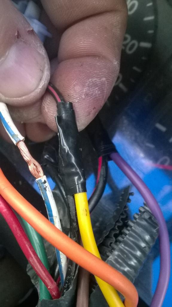
Small Black/Red Stripe Wire=Main Power to ECU
Red Wire=Power to AC/HEAT
White/Blue Stripe=Radio
Connect YELLOW wire from Alarm to small BLACK/RED STRIPE.
Now you have TWO Options
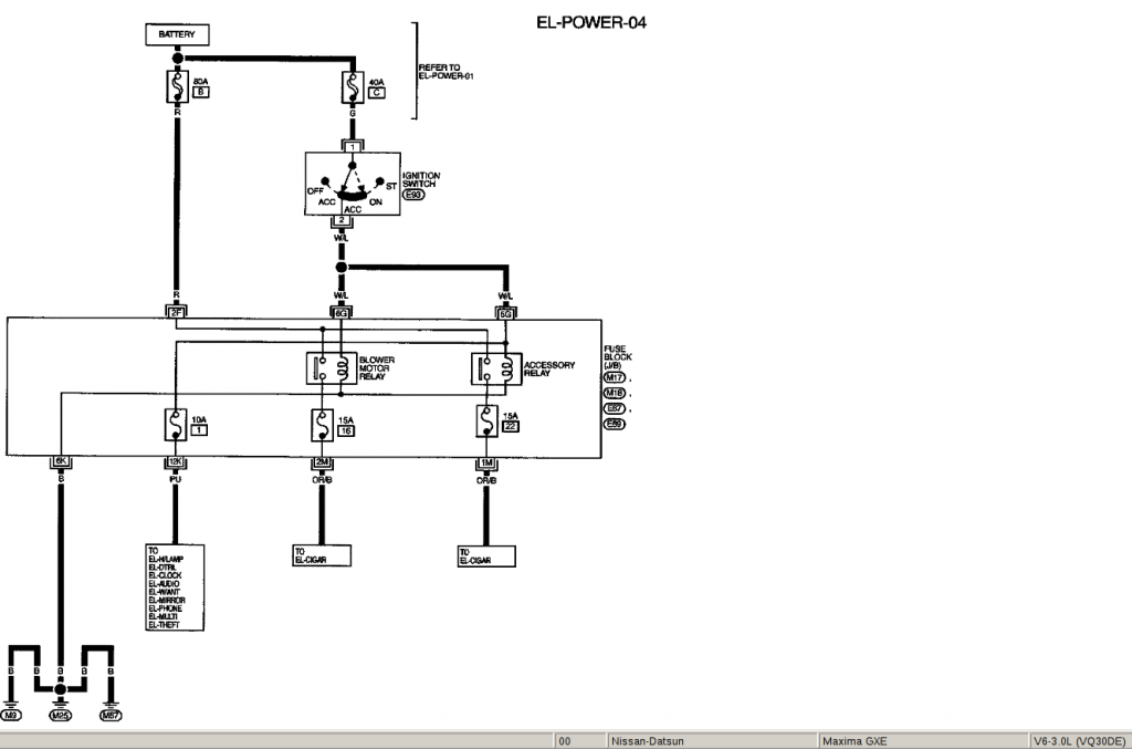
There is only ONE ACCESSORY wire left from the alarm to turn something on, the ORANGE.
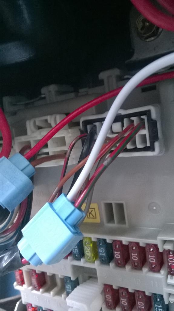
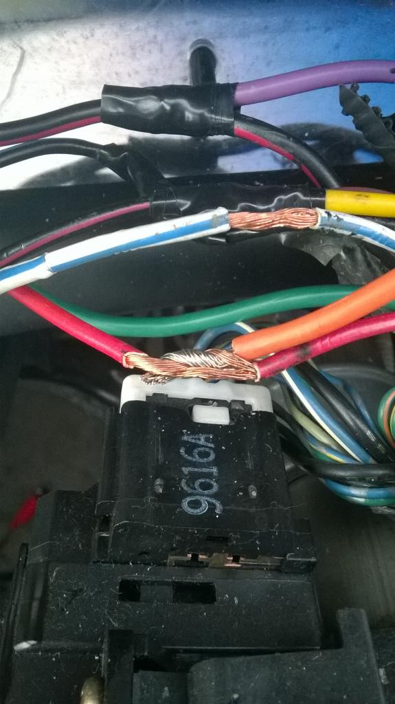
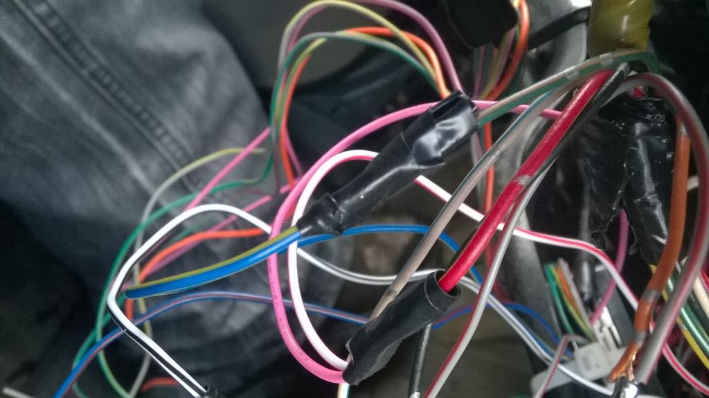
In the picture you see a SOLID RED wire and WHITE/BLUE STRIPED.
SOLID RED TURNS ON POWER TO THE HVAC
WHITE/BLUE STRIPE TURNS ON RADIO/LIGHTER
You can either connect the ORANGE wire to both WITH or WITHOUT a relay to isolate the two wire from one another when the key is used to start the car OR connect the ORANGE wire to the SOLID RED wire so your AC/HEAT will power up with the remote start.....its your choice.
I dont need my radio running if im not in the car so I choose to have my Heat/AC instead.
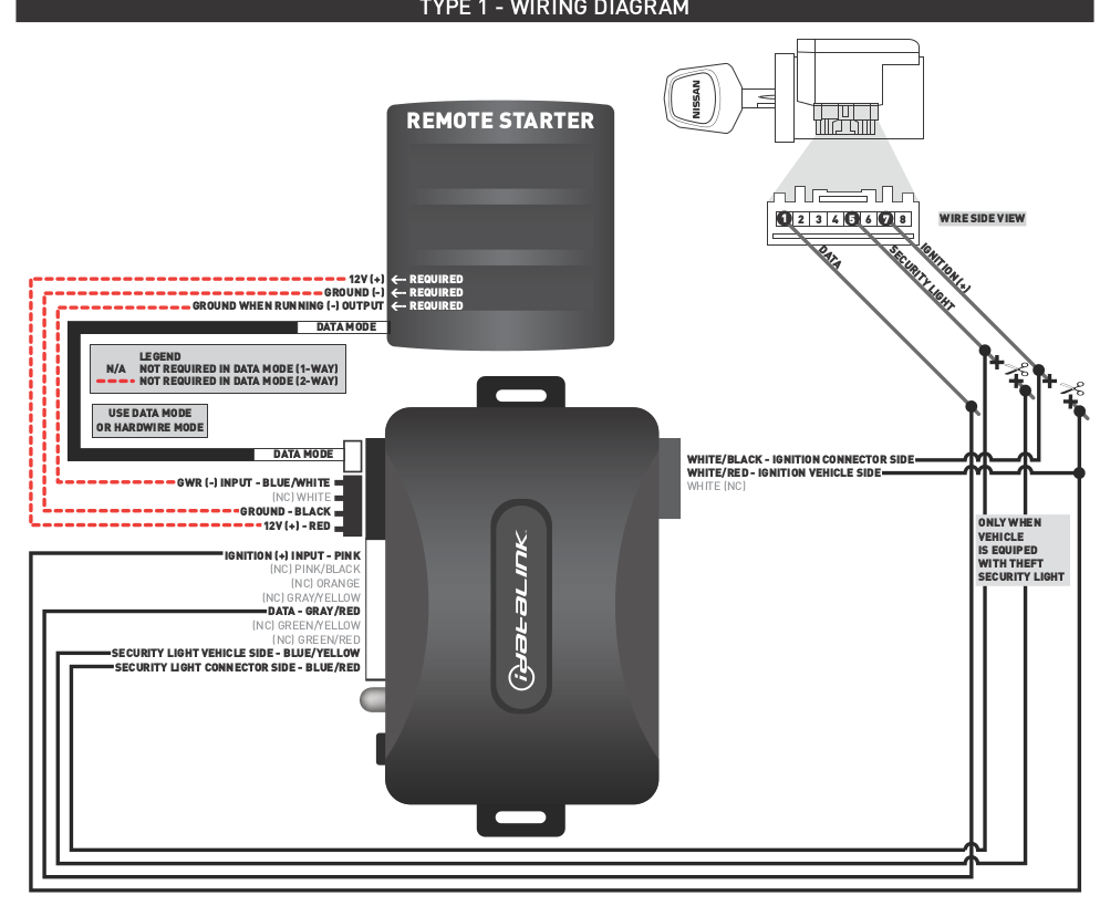
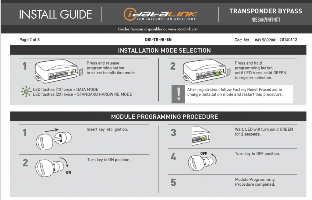
This is how the Bypass Module installs Only Solid Black Wires on the diagram are used. The Doted Red lines are not needed. DONT FORGET TO PROGRAM OR HAVE PROGRAMMED THE BYPASS MODULE
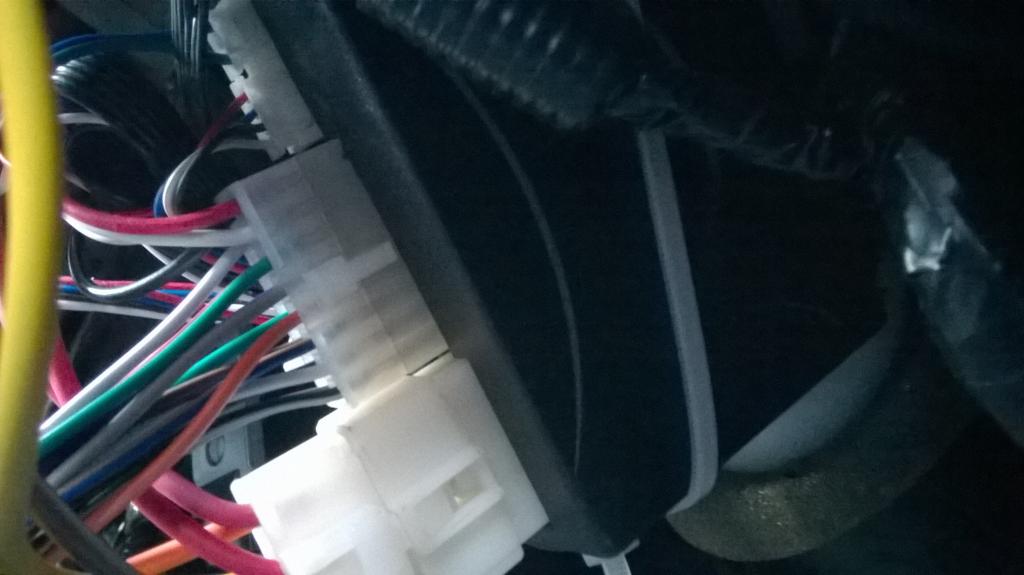
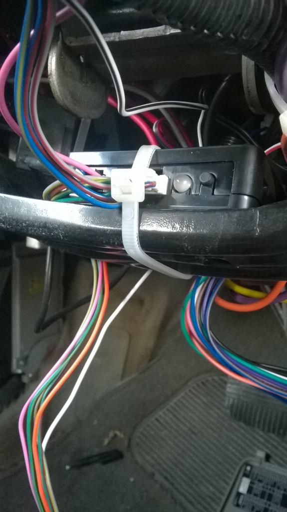
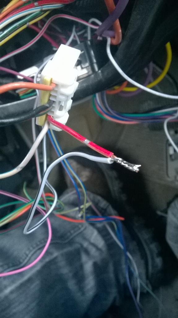
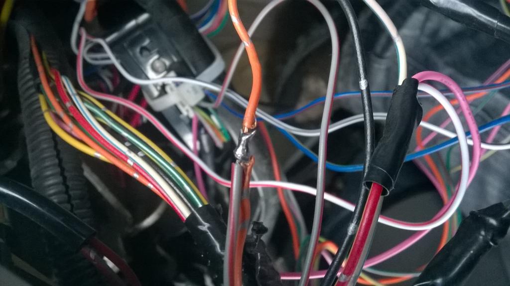
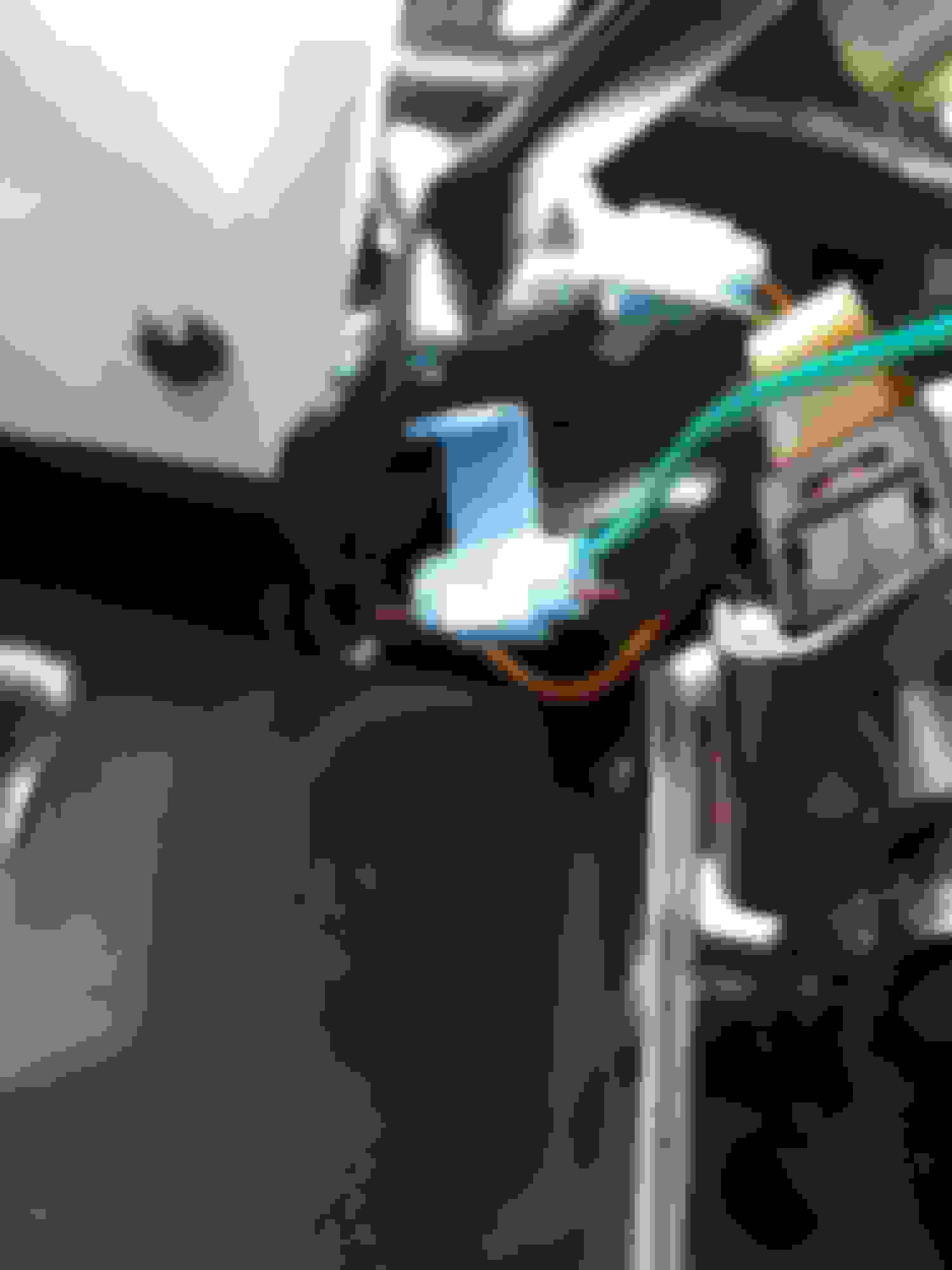
First your going to locate the RFID/Transponder Key Harness. It is connected to the BLACK BOX on TOP of the Ignition cylinder.
You will see a
ORANGE WIRE=Data
RED/YELLOW STRIPED WIRE=Ignition
GREEN/ORANGE STRIPPED WIRE=Security Light
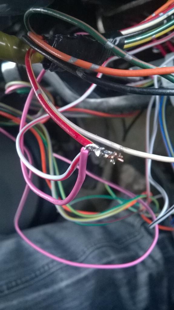
You Cut the IGNITION WIRE and SECURITY LIGHT wire about 2-3 inches away from the plug.
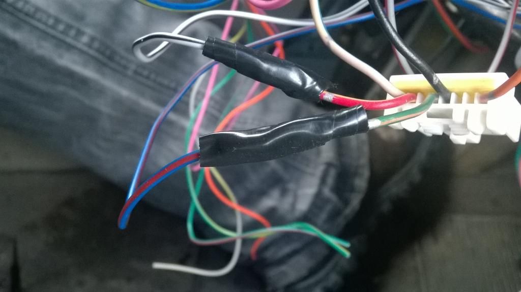
Connect the PINK wire and the WHITE/RED STRIPED wires from the Bypass Module and connect both of them to the IGNITION CAR SIDE of the wire not the PLUG SIDE.
Now connect the WHITE/BLACK STRIPPED wire from the the Bypass module to the IGNITION PLUG SIDE of the of the wire.
Next Connect the BLUE/RED STRIPPED WIRE from the Bypass module to the SECURITY LIGHT PLUG SIDE WIRE
Now Connect the BLUE/YELLOW STRIPPED WIRE from the Bypass Module to the SECURITY LIGHT CAR SIDE WIRE
Now Splice the GREY/RED STRIPPED WIRE from the the Bypass Module to the ORANGE wire from the plug any place you can. YOU DO NOT HAVE TO CUT THE ORANGE WIRE FROM THE PLUG LIKE THE OTHERS
Connect the DATA Cable from the ALARM to the BYPASS MODULE just like in the first picture.
Now you can Program the Bypass module to a Single Key.
Mind you this is an install on a 2000-2001 Automatic.
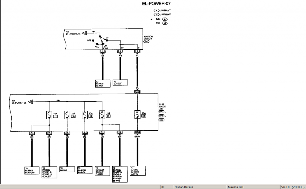
From Bulldogs site "NOTE *1 When Installing a REMOTE STARTER, you MUST use BOTH Starter #1 and Starter #2 wires. Both wires must be connected to the STARTER/CRANKING Output wire from the Remote Starter or the vehcile will NOT Remote Start when the Engine is cold."
Nothing on that sheet that says anything about what your referring too.
BY THE WAY....EVERYONE PLEASE DO NOT USE THAT PAGE TO DO YOUR WIRING......THOSE WIRE COLORS DO NOT EVEN EXIST ON OUR CARS
I'm not going to argue with you, It has been hooked up just like I have posted and guess what ....IT WORKS.
Once AGAIN.....
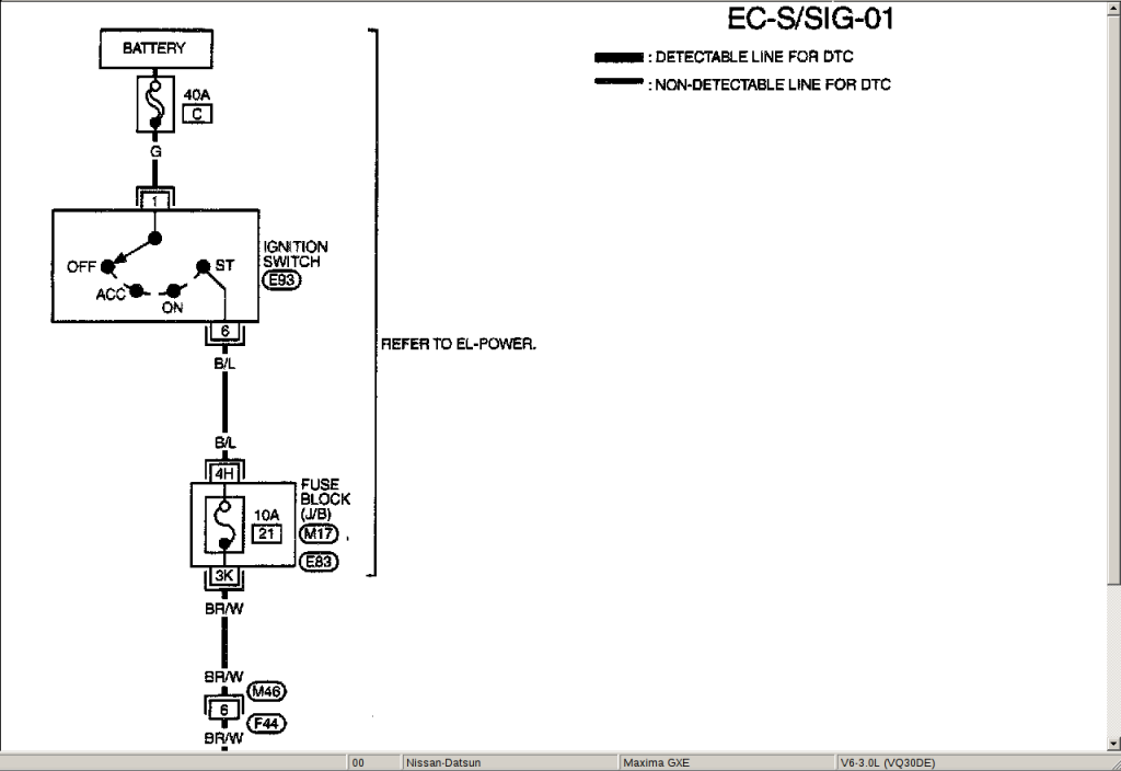
ALLData even shows you
TWO SEPERATE START WIRES....Look in the top right of the screenshots...You will clearly see 01 and 02,
01 shows Black/Blue Wire also known as B/L on a schematic.
02 shows Black/Red Wire also known as B/R on a schematic.
Ok I have done some more to this alarm.
Connect the Horn
In the steering cluster you will see a YELLOW PLUG, In that plug you will see a Green/White wire, Connect the Brown/White wire from alarm to the Green/White wire and now you have horn.
Next is the Brake switch.
There is TWO brake switches connected to the pedal
Hook the Green/White from the alarm to the Red/Green wire from the all black brake switch connector.