Where do these lines run to?......
#1
Where do these lines run to?......
just finishing up the vq35 swap and have a couple questions as to where some of these lines run to....
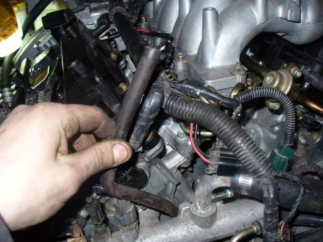
This line comes from the tranny to.....?
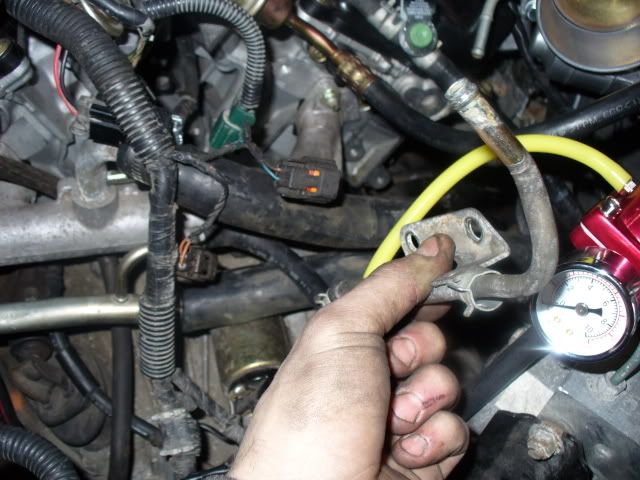
From the coolant bar to ?
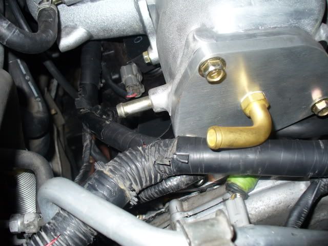
These go?
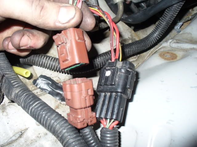
Before i did the swap nissan told me the ecu and engine harness were fried so i got a new ecu and a harness. My car is a 99' and this harness came out of a 97'. The new clip on the harness did not fit into this clip, but i still have the old clip from the original harness that fits. The clip that fits only has 6 wires while the new clip has 8 wires. How would i splice this clip into the new harness so it works?
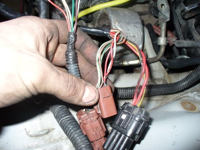
This line comes from the tranny to.....?

From the coolant bar to ?

These go?

Before i did the swap nissan told me the ecu and engine harness were fried so i got a new ecu and a harness. My car is a 99' and this harness came out of a 97'. The new clip on the harness did not fit into this clip, but i still have the old clip from the original harness that fits. The clip that fits only has 6 wires while the new clip has 8 wires. How would i splice this clip into the new harness so it works?


#2
Number 1, that's a vent tube for the trans, just leave it open.
Number 2, no idea. TB, maybe?
Number 3, the back port is for the brake booster IIRC, and your butterfly plate looks like it was put in backwards or something (is that even possible?). Shouldn't that vacuum line run forwards? Then again that looks rather large, maybe I'm looking at things incorrectly.
For the last pics, consult the FSM for a wiring diagram.
#4
not too much help from the FSM for the last picture. All i have is the haynes manuel and it doesn't help with the wire colors off that clip or which wire colors are the same for 95-98 and which are different for the 99s. Anyone care to help that has a manuel that goes more in depth? or know where i can go to find out what colors i can cut and splice together so that it works??
#5
not too much help from the FSM for the last picture. All i have is the haynes manuel and it doesn't help with the wire colors off that clip or which wire colors are the same for 95-98 and which are different for the 99s. Anyone care to help that has a manuel that goes more in depth? or know where i can go to find out what colors i can cut and splice together so that it works??
http://forums.maxima.org/showpost.ph...0&postcount=36
#7
yeah thats exactly what i thought but they told me the ecu runs a nads code if thats the problem...i didnt think when its an immobilizer issue it even ran a code for it. just thought the ecu locked up. but the tried everything and wanted me to pay 4100 to fix it so i said forget that ill do it i'm doing a swap anyway.
#11
Ok sorry I lied about doing it last night.  But I'm honestly going through the EC section of both FSM's right now and writing down anything that goes through the F36 connector (the brown connector on the engine control harness). I will be posting my findings shortly.
 But I'm honestly going through the EC section of both FSM's right now and writing down anything that goes through the F36 connector (the brown connector on the engine control harness). I will be posting my findings shortly.
#12
man you are a life saver, we looked and looked through the manual and the wiring diagrams in the back just look completely confusing lol but i really appreciate this !
#14
you really are a lot of help i appriciate it all thanks bro.
#16
Looks like you're going to have to rewire both connectors. Some of the connections that went through the brown connector in 1997 go through the black connector in 1999 (like o2 sensor/CPS (POS)/MAF power, etc). This is gonna take a bit longer than I thought....standby.
#19
Looks like you're going to have to rewire both connectors. Some of the connections that went through the brown connector in 1997 go through the black connector in 1999 (like o2 sensor/CPS (POS)/MAF power, etc). This is gonna take a bit longer than I thought....standby.
#20
F36 = brown connector
F37 = black connector
For instance F36-1 = connector F36, pin #1. I will provide the pinouts for both connectors at the bottom.
Turns out most of the connections that need to be moved are irrelevant or redundant. These are the ones that are left to move:
o2 sensor power - Needs to be moved from F36-6 to F37-6. The wire that needs to be moved is red with a black stripe. You will be splicing it into a red wire.
ACRLY (a/c relay coil) - Needs to be moved from F37-6 to F36-6. They will both be black with a red stripe.
Fuel injector power - In a 97 the wiring has the ignition switched power to the ECU and injector power running through 2 seperate wires. The 99 wiring has both going through the same 20A fuse. You need to combine wires 2 and 5 in the 97 F37 connector in this manner: Cut F37-2 and tap it into F37-5, and not the other way around. This will send power to both the injectors and ECU pin #24 through 20A fuse #34.
----------------------------------------------------------------------
These wire splices are plug and play as far as retaining the 99 F36 connector is concerned. Just cut them off of the 97 and move them into the same position on the 99 connector:
F36-2 (white w/ black stripe)
F36-3 (light green)
F36-4 (light green w/ red stripe)
F36-5 (white)
F36-7 (red)

These pinouts are on the terminal side of the connector, not the harness side. If you have any more questions feel free to ask.
F37 = black connector
For instance F36-1 = connector F36, pin #1. I will provide the pinouts for both connectors at the bottom.
Turns out most of the connections that need to be moved are irrelevant or redundant. These are the ones that are left to move:
o2 sensor power - Needs to be moved from F36-6 to F37-6. The wire that needs to be moved is red with a black stripe. You will be splicing it into a red wire.
ACRLY (a/c relay coil) - Needs to be moved from F37-6 to F36-6. They will both be black with a red stripe.
Fuel injector power - In a 97 the wiring has the ignition switched power to the ECU and injector power running through 2 seperate wires. The 99 wiring has both going through the same 20A fuse. You need to combine wires 2 and 5 in the 97 F37 connector in this manner: Cut F37-2 and tap it into F37-5, and not the other way around. This will send power to both the injectors and ECU pin #24 through 20A fuse #34.
----------------------------------------------------------------------
These wire splices are plug and play as far as retaining the 99 F36 connector is concerned. Just cut them off of the 97 and move them into the same position on the 99 connector:
F36-2 (white w/ black stripe)
F36-3 (light green)
F36-4 (light green w/ red stripe)
F36-5 (white)
F36-7 (red)

These pinouts are on the terminal side of the connector, not the harness side. If you have any more questions feel free to ask.
Last edited by nismology; 02-14-2008 at 03:50 PM.
#21
thanks a lot nismology. after we do that and bleed the clutch were going to try to fire the car up tonight. It probablly wont start because of the new ecu. I was told i have to get my key reprogrammed because of the immobilizer.
#24
yea 99 fed spec 5 speed ecu. we tried cranking it and it just cranked for maybe a second everytime. tried pulling codes to see if there was a nats code and the scan tool just said error. Is that big or does it just need to be programmed because its a new ecu?
#25
'99, then yes, you'll have to get the key and ECU programmed at the dealer.
#26
and until it gets reprogrammed the car acts like it doesn't have any computer at all and will barely crank correct? and you dont know how much nissan charges for the reprograming of the ecu and key as well i'm guessing because if the immobilizer?
#27
It'll crank, but it won't fire.
Thread
Thread Starter
Forum
Replies
Last Post
hez8813
5th Generation Maxima (2000-2003)
11
03-12-2020 12:06 AM
ballerchris510
3rd Generation Maxima (1989-1994)
9
09-10-2015 09:35 PM


 The immobilizer info probably just needed to be reprogrammed to the ECU.


