Does anyone have a site for rebuilding an amp?


 01-06-2006, 09:54 AM
#42
Senior Member
Thread Starter
iTrader: (10)

Join Date: Jun 2004
Location: Danbury, CT \ Rochester, NY
Posts: 2,598
When I get back to school, I'm going to take out that resistor, and I will post pics of how the board looks. It's hard to tell exact damage on the board, so I'm going to wait to see what's underneath the resistor.
01-17-2006, 08:53 PM
#44
Senior Member
Thread Starter
iTrader: (10)
Join Date: Jun 2004
Location: Danbury, CT \ Rochester, NY
Posts: 2,598
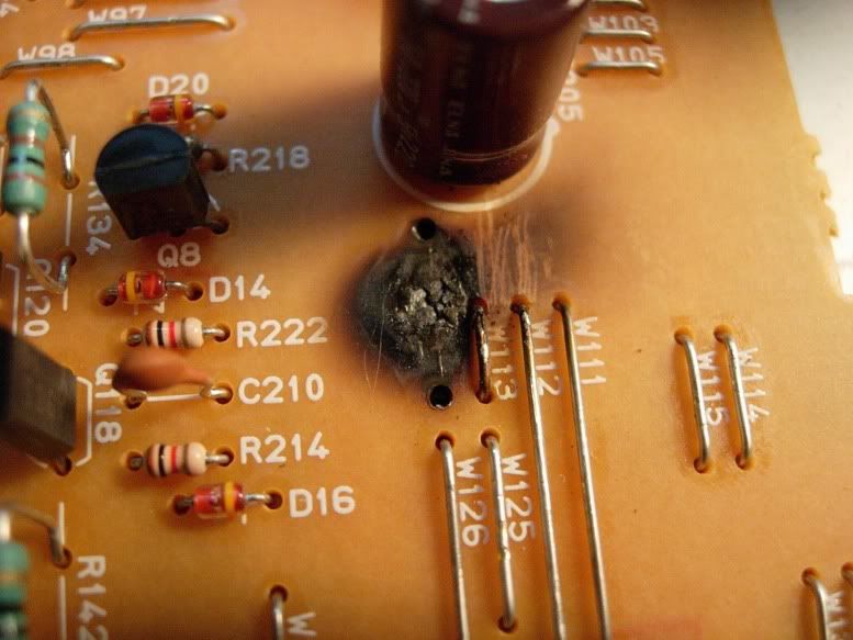
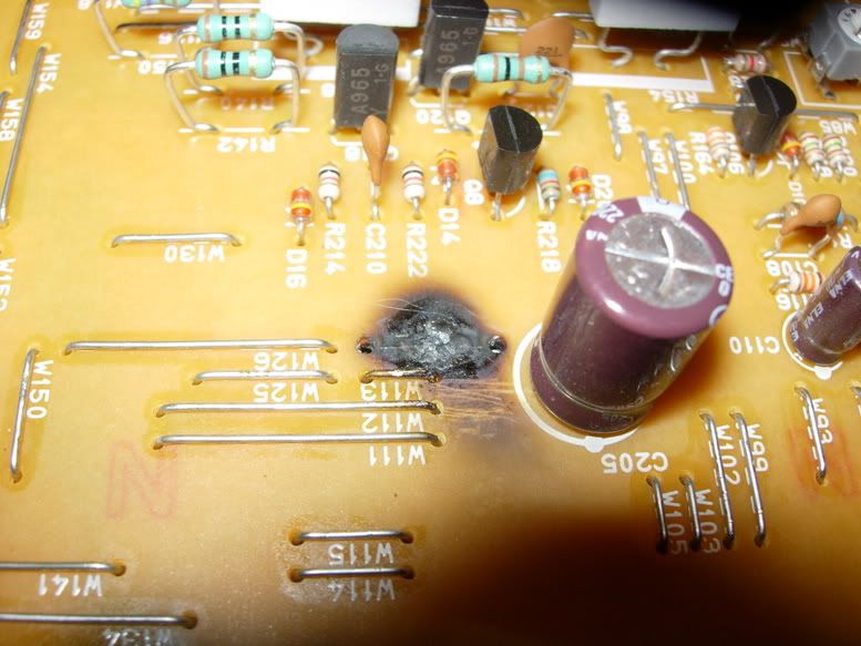
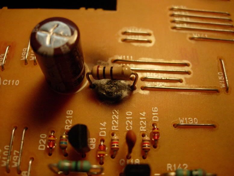
Just got back from taking that resistor out. It looks to be a 10 ohm resistor, so I will either buy/have one of my friends take one from their lab a 1/2 Watt, 10 ohm resistor. The board is burned, but I am going to keep my eye on it to see how it goes. Here are two pics after taking that resistor out. Another note: one of the solder points literally popped off without any heat, so there wasn't a great connection either.
01-18-2006, 08:56 PM
#46
Senior Member
Thread Starter
iTrader: (10)
Join Date: Jun 2004
Location: Danbury, CT \ Rochester, NY
Posts: 2,598
I will look into it tomorrow, good catch. I don't keep the amp in my room anymore since it was a pain to carry it to the room where I would work on it.
On another note, my friend should be getting that resistor from a lab at school (we figure paying 30g's for college should justify a 50 cent resistor) soon, and we'll have it back together in no time.
If I remember correctly, my friend said that not only the casing was cracked, but the resistor was as well. It was completely shot. I'll post another update when I look at W113, or when I get that new resistor in. THanks for the look.
Man, I just hope this thing finally works andI get to hear my sub at a fraction of its potential...without setting anything on fire as I've been warned...
01-22-2006, 12:02 PM
#48
Senior Member
Thread Starter
iTrader: (10)
Join Date: Jun 2004
Location: Danbury, CT \ Rochester, NY
Posts: 2,598
Fixing my amp was a success…sort of. I still haven’t been able to try it out, and see if the problem is taken care of. Basically, everything that I thought was wrong with this resistor point, is fixed. Whether or not this was the only problem with the amp will determine if we actually fixed it or not.
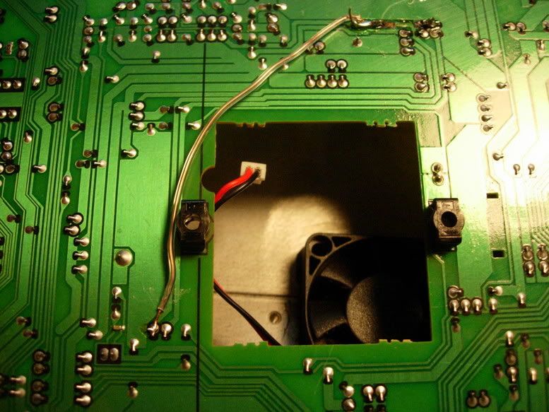
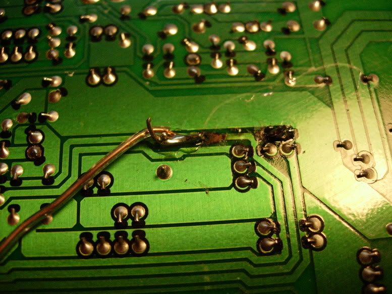
Basically, we figured the resistor to be a 10 ohm resistor, � watt. Just as I was readying myself to solder the new resistor in (I thought this was the only task we had to do in order to fix the problem), I noticed that the underneath original solder points, the copper “lines” (for lack of a better word) had been lifted. In the following diagram, these are the red x’s.
The rest of the symbols are as follows: Red X – broken copper line; Silver dot – unaffected solder points; Black Dot – Original solder points for the burnt resistor; Green line – copper lines.
What we did: Since the original solder contacts were messed up, we soldered the left resistor point to the silver dot on the left. For the right contact, we soldered directly to the right solder point (on the green line with the rightside black dot). Because the line was broken at the solder points, we took shielded wire, and connected the left side solder point, to the next available solder point on the board, following the copper lines downward. All this can be better described with the pics.
I also forgot – when I said that these guys worked on their computers, I forgot to say that their major is actually electrical engineering, so this was right up their alley. I only remembered this when my friends knowledge showed itself when explaining everything to me.
In all, I learned A LOT from working on this board, and my only hope now is that the sub is powered when I install the amp again in two weeks or so when I go home (my car was too packed to carry my sub, and I couldn’t care less since this amp didn’t work and my old one is a piece). Thanks for everyone’s help and patience, and I will update this thread yet again when I get to test out the amp.
01-22-2006, 03:24 PM
#50
Senior Member
Thread Starter
iTrader: (10)
Join Date: Jun 2004
Location: Danbury, CT \ Rochester, NY
Posts: 2,598
Originally Posted by Cant_Get_Ryte
cant wait to see the results, just keep an eye on it with the back open for a while before pushing it hard or walking away from it 
01-23-2006, 08:54 PM
#51
Senior Member

Join Date: Feb 2005
Posts: 289
You could have used a stress relieve mount for the resitsor bc it it bigger than the lenth of the holes. You couldn't find any micro components instead of mini components. Also, what type of board is that? I work with epoxy boards everyday, and you could have fixed the burn marks if you had more time. I love to see other people trying to fix their things with the same things I have to fix everyday. So what exactly does classes of the electrical engineering. I want to work towards this as a carerr. Just wondering.

Thread
Thread Starter
Forum
Replies
Last Post
BPuff57
Advanced Suspension, Chassis, and Braking
33
04-16-2020 05:15 AM
Pied
4th Generation Maxima (1995-1999)
0
09-26-2015 03:29 PM