

4th Gen TCU Wiring


4th Gen TCU Wiring
Sorry for all the threads lately, but it's becoming crunch time with some of my projects, and things are left unclear when explained originally or by the FSM. I have been using certain plugs in the engine bay as a source for wiring as far as the transmission goes (for shift_fast, for example) but want to switch to easier-to-work with TCU wires.
However, these wires don't appear to be the same in color, so I can't locate them. The wire colors match on the plugs in the engine bay, but don't seem to on the TCU (the TCU is the little black box on top, not the metal one on the bottom, right?).
Looking at the FSM, page AT-19, those are the wires I'm looking for. I can't find anything that seems to match though. A few wires match in color, but they aren't near each other like you'd think they would be. For example, solenoid "B" is light green/black as it says in the FSM for the plug in the engine bay. There does not appear to be a single light green/black wire on ANY of the plugs going into the TCM, let alone the plug that I think is correct.
So am I identifying the TCU correctly, and does anyone know which of these plugs has these wires and what color they should be?
Originally Posted by Kevlo911
Check the color of the wires at the joint connector(there is a connect inbetween the tranny and the tcm)
I thought the wires were consistent in color throughout the whole harness?

Originally Posted by Tatanko
I did, that's the "plug" I'm referring to. That's where I had been tapping into the wires. Only SOME of those wires appear to match up on the TCM. For example, on the TCM wiring, I don't see a light green/black wire like I do on the joint connector (which is the wire for solenoid B).
I thought the wires were consistent in color throughout the whole harness?
I thought the wires were consistent in color throughout the whole harness?
Check meh edit. I would assume they are but who knows with Nissan...
Originally Posted by Kevlo911
TCM looks like a mini ECU BTW, the connector input is blue.

Also, AT-10 for the 1995 FSM doesn't have a pin diagram on it
Originally Posted by Tatanko
Ugh. No wonder. I'm looking at the wrong unit
Also, AT-10 for the 1995 FSM doesn't have a pin diagram on it
Also, AT-10 for the 1995 FSM doesn't have a pin diagram on it

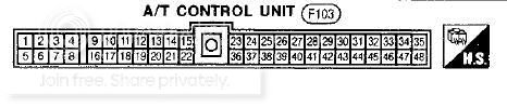
Big pic but w/e


I think I have it figured out. Keyword: think.
Sorry for the blurry pic, but:

Realizing that it's a tiny bit sideways, I assume that the wires go..
1 3 5 7...
2 4 6 8...
Like that, rather than straight across numerically. Am I right? If so, the wires match up. I can't seem to locate a green/black wire for the torque converter though in the location it says it should be
Sorry for the blurry pic, but:
Realizing that it's a tiny bit sideways, I assume that the wires go..
1 3 5 7...
2 4 6 8...
Like that, rather than straight across numerically. Am I right? If so, the wires match up. I can't seem to locate a green/black wire for the torque converter though in the location it says it should be
Originally Posted by nismology
Oh snapes...didn't realize the POS you posted before had the pinout. 
Ahh, after countless interruptions, I got wiring in place for the torque converter (two wires and a 12v source). It got dark then, though, and I was tired, so I called it quits for the night. Now that everything is prepped and I have the knowledge, now, the rest of my wiring should all get done tomorrow.
Originally Posted by Kevlo911
Sweet lemme know how it works.


Thread
Thread Starter
Forum
Replies
Last Post
MAXSE5SPD
General Maxima Discussion
33
Sep 17, 2022 04:00 AM
Finkle
4th Generation Maxima (1995-1999)
13
Sep 27, 2015 09:53 PM
ViciousVQ30
4th Generation Classifieds (1995-1999)
0
Aug 5, 2015 05:40 PM