
96 ECU Pin-out Diagram


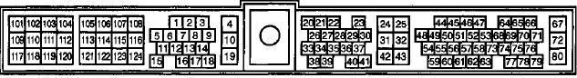


This post is rather old, but i found it while searching for some pinouts for the ecu and some other connectors. This thread hasthe ecu pinout in a good picture so lets pull it up rather than start acompletely new thread.
Firstable, some background, im swapping a VQ20DE (basically the same as a VQ30DE) accompanied with a 350z tranniy into a 200sx. The wireing is currently in process and i needed some information on the connectors on the car. I have the 1995 and 1996 4th gen FSM's, but i cant find the following in them:
- Ecu pinout with colors and descriptions. (got that one from above)
- Pinout for the obd2 connector. What i want to kow if there are CAN etc. lines to hook up for me also. (strange, since my ecu doesnt even have a wire on pin 69 which should be the obd2 datapin+?).
- Pinouts for the F36/E13 and F37/E14connectors since they are the main ecu powersupply.
- Pinouts for the other connectors on the cabin side of the ECU harness. I have two unended, and two of the connectors with a resistor of some kind at the end. Basically F100 to F110 is the range.
- Probably a ****load of other stuff also, but those are the ones i need to start with.
I would be very happy if someone could give a pointer or even actual pinouts /w colors for those connectors, would make my life way easier

Senior Member
Joined: Aug 2005
Posts: 856
From: MASS
You can DL your own from www.VQ35DE.com/ESM.
- Ecu pinout with colors and descriptions. (got that one from above)
- Pinout for the obd2 connector. What i want to kow if there are CAN etc. lines to hook up for me also. (strange, since my ecu doesnt even have a wire on pin 69 which should be the obd2 datapin+?).
- Pinouts for the F36/E13 and F37/E14connectors since they are the main ecu powersupply.
- Pinouts for the other connectors on the cabin side of the ECU harness. I have two unended, and two of the connectors with a resistor of some kind at the end. Basically F100 to F110 is the range.
- Probably a ****load of other stuff also, but those are the ones i need to start with.
EC:8+ has the entire ECU pinout.
EC:95 has the connector pinouts from above(the section is called Main Power Supply Circuit...)
All other connectors are explained in either EC or EL, sometimes both.
Partial DLC pinout is EC:7
Last edited by pmohr; Feb 18, 2008 at 05:28 PM.
http://www.7-zip.org/
WinRAR will open it just fine, unless you have an old version. How does it 'not like it'? 7z is a crap compression algorithm IMO. All archivers I've seen that support 7zip have to actually decompress all of the files, even when you just want one file out of the archive.
bzip2 and tar for me, kthx.
bzip2 and tar for me, kthx.
 Yeah, I figured it out, thanks! I must have an old winrar because it doesnt recognize the 7z at all.
And for example, if there was a simple plug with a descriptions for the pins, it would be way easier to trace the lead for lets say pin 20 which is forthe startersignal.
The reason im asking is because 1.) it wouldmake things a lot faster, and 2.) i would reallyknow what those additional unconnectedplugs are for.
From last nights work, i have two additional questions:
1.) What does it mean when the DLC blinks when i turn the power on, it just blinks, it's not giving any codes with different intervals.
2.) My engine is a VQ20DE, does it have an OBD2 aswell because i seem to be missing the whole wire on ecu ping#69?
Im a bit lost with this now. Firstable, the ecu _seems_ ok, meaning it can flip the ECU etc relays, it can use the idle control, it reads all the sensors and gives spark. But the problem is that i dont have the injector ground pulse at all. Could someone that knows more about the VQ setup tell some things that could cause the injectors to stop working but still retain the coils fireing the plugs etc. Help would be greatly appreciated at this point since that is basically the only real problem between meriding the car and this state.
Im a bit lost with this now. Firstable, the ecu _seems_ ok, meaning it can flip the ECU etc relays, it can use the idle control, it reads all the sensors and gives spark. But the problem is that i dont have the injector ground pulse at all. Could someone that knows more about the VQ setup tell some things that could cause the injectors to stop working but still retain the coils fireing the plugs etc. Help would be greatly appreciated at this point since that is basically the only real problem between meriding the car and this state.
By UIM you mean the Upper intake manifold, right? Well i have two grounds going to the Lower im where it meets the upper intake. As far as i know (and trust me im getting to know this harness pretty well) those are the only grounds on the actual ECU harness, correct?
I also checked that all the pins on the that are supposed to get ground, also get it, so grounding shouldnt be and issue as far as the ecu is concerned. The injectors are also working when ground is manually applied to one, and also all have 11,1 to 11,3 ohm resistances. This is just a weird problem really.
All the position sensors should be ok, since i disconnected and displaced them all one by one, and each one also cut the coils fireing...
The ecu harness is ok, i measured the leads holding the injector pulse and they are also all ok.
Yeah, ill see if im missing grounds, but i doubt its that anymore since i've checked, and triplechecked and measured them to be correct.
I just realised that the max uses simultaneous injection when starting, and switches to sequential when the engine is running. So, what is the point of change, and could it be that because i dont have the starter signal to ecu pin 20, the engine wont inject at all because it thinks its in run -more instead of startmode, and the rpm is just too low/unstable for a sequential when starting?
Also, it might ofcourse be that everything in actually in order and the injectors are fireing, but simultaneously. But since i have been looking and listening to some sequential, 6 clicks to 1 spark ratio clicking, i might not even have recognised them to be injector sounds. (The starter makes a real noise). This is option nr2, i think the starter wire to pin 20 has more to do than just retard timing... Any info on this one?
ECU doesn't see the engine running, it kills the pump and cuts the injectors. Could be a problem, or it isn't reading a tach signal (don't quite remember what it uses to sense if the engine's running, I imagine it would be a tach signal).
So the starter wire also bypasses these shutdowns to get it run (maybe, dont know how much rpm's the engine gets when its pop started?)
Hmmh, ill just try and hook up the starter lead and see if it has any effect. Ill 'report' back tomorrow Thanks for the superquick advice, its very nice to get some second sights and opinions
Hmmh, ill just try and hook up the starter lead and see if it has any effect. Ill 'report' back tomorrow
Thanks for the superquick advice, its very nice to get some second sights and opinions
Ok, so lets put out some 1st hand info here then. I hooked up the starter signal to pin 20, which is btw found on both F37/F36 connector and inside the car. Injectors fire now I knew i had to hook it up, but i was too eager to troubleshoot the injectors so ididnt even hook it up at first
Now for the pump relay (might make a loopback through the now unused start signal to the bay -lead).
I knew i had to hook it up, but i was too eager to troubleshoot the injectors so ididnt even hook it up at first Now for the pump relay (might make a loopback through the now unused start signal to the bay -lead).
Well to add to this discussion, i now get the engine running for a while, but it then cuts the injectors and just shuts down. I've tried disconnecting all three position sensors, crank rear: wont start at all, cam: wont start at all, crank front (ref): has no obvious effect. Tried two different crank front sensors, the harness is working all the way. Im starting to get desperate, any pointers on what might be wrong?
I have the fuelpump running all the time.
The engine runs very smoothly for a few seconds,
I do have a few airleaks but they would also cause a rough idle, this is more like a direct cut-out like flipping the key.
I have grounded the fan and pump signals in order to let the ecu think its using them properly.
I do not have the rpm signal hooked up to the tach, would this matter?
Please, could someone tell me if the engine can run for more that a few seconds without the front crank sensor attached? My ecu (weird?) lacks diagnostics so i cant really get the codes. just a simple yes or no is enough.

Thread
Thread Starter
Forum
Replies
Last Post
Omar Abdurrahman Siddiqi
5th Generation Maxima (2000-2003)
33
Aug 26, 2016 05:18 PM
BLACKKILA.GTR
5th Generation Classifieds (2000-2003)
1
Sep 29, 2015 11:23 AM
QueensMAX
5th Generation Maxima (2000-2003)
7
Sep 15, 2015 04:14 AM