When you click on links to various merchants on this site and make a purchase, this can result in this site earning a commission. Affiliate programs and affiliations include, but are not limited to, the eBay Partner Network.
Did your CAI upgrade and need help with a few items left open. Can you help with telling me where to route the other end to or plug the opening and with what.
This under the tb. Used to run to the Aav. Where to now or plug it at the source?
Behind tb to the right, on the intake left of EGR Valve. Where 2 or plug here?
Ok .5in hose from under side of im connects to airbox, where 2 now or plug?
Directly behind this is another 1\2 open port that used to run to front lower exhaust. Where 2 or plug?
Not sure what this u is used to run to last section of 3" pipe just below tb. Where 2 now or block?
Pcv valve? Has male plug on other end? Where 2 or plug?
Do i need to keep this? Look like o2 sensors? Connect to what if need?
Last edited by lowpost99; Aug 21, 2015 at 08:08 AM.
well you should only have 3 hoses on the intake, leave anything on the TB those are vacuum lines, now for the intake, the one on the back is for cold start, and idle control, metered air, (needs to go after maf) you will need that, the front is crank case ventilation you will need that and it is metered air and the 3rd goes to the charcoal canister which vents fumes from the gas tank. The last part is exhaust parts, you have two choices on those 1. get a small filter and put on the intake part and leave 2. remove which you will need to block off the hose that goes to the exhaust, all it does is allow air into the exhaust when there is a vacuum in the exhaust system. if you need more let me know and I can go look on my car where the vacuum lines go and such....
So
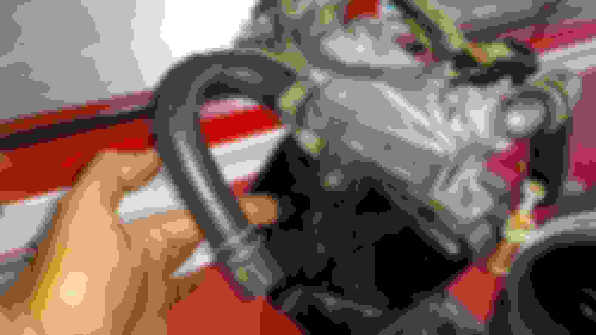
yes any more help is appreciated, in this pic my friend is point to those two 3/8 vacucum lines which come to same tee and line I'm holding the other end which came off one of the two things with the electrical connections to the plug bundle that the MAF uses.
Front and back other end was on next pic
This is where the tee line in my hand went. Should i pipe this into my new cai north of the maf? Same for the next big pipe from under the intake?
Last edited by lowpost99; Aug 21, 2015 at 03:21 PM.
The metal male end was plugged/ported into the old3" line port this into new cai? Hes pointing to the other end on the valve cover idk what that is.
that one goes to the intake after the MAF it is the inlet for crank case the outlet is on the back valve cover and goes into the intake with the PVC valve mounted on the intake
So
yes any more help is appreciated, in this pic my friend is point to those two 3/8 vacucum lines which come to same tee and line I'm holding the other end which came off one of the two things with the electrical connections to the plug bundle that the MAF uses.
OK so you didn't delete the AAV. I see it, but it looks like you removed it and those towers with the vac lines and electrical connections. Are they remounted on something else now? Help I thought these get deleted.
Also, I see that connector gave you issues too.
What's the pin out for the connection at right of the throttle body? That connector gave me issues and I pulled the wires out before taking note.
yea I moved both and just mounted them to where the air box bolted in, you have to unbolt the last bolt and bend out the pipe that goes to the exhaust or get a new hose to reach from where you put it, it can be removed, you would have to plug the pipe going into the exhaust and plug the vacuum line going to it, are you talking the TPS, it didn't give me issues the boot was cracked so I just taped it up to keep the plug protected. I will a pix of the FSM so you can see what those parts do.....
I could use the pin out for that trottlebody electrical connector and what type plug to figure how to push the pins in or out.
Give me a little bit to look over your pictures. It's been some time since I had any of those emissions devises under the hold lol.
The connection on you throttle body is Throttle position switch. The bottom pin is idle signal out to ECCS. The middle pin is 12v in from ECCS and the top pin is WOT (wide open throttle) signal out to ECCS
If the idle and wot are mistakingly reversed, would I choke around 3k rpm when accerating ....like on the throttle heavy? It either that or my TB or bccd vac lines are reversed on the solenoids.
flipped idle and WOT pins would do exactly that. but dont swap the pins around just yet. i can see in the pic that the pins are pretty corroded. mine did that too, it went into limp mode and wouldnt rev past 3k. thats a nissan "safety feature". i cleaned my pins with a very small file and put dielectric grease in the connector. completely resolved the issue. that was last september. its just now starting to lose idle contact again. im about to switch to a new style throttle switch with a better seal connector so that hopefully I wont have to deal with that problem again. sorry for the late post, work has kept me especially busy this week.
How to pop out the old bolt gaskets on valve cover...
The new grommets at the bottom came with the Felpro kit. The old one are in the middle still inside the metal caprings that the bolt heads rest upon. How do remove n replace these? Also I'm uncertain, but my searches lead me to believe that the 3/4 o ring is for something to do with my spark plugs.... thx for help as always.......
Edit: Vice n hammer....twisted the grommets on to get about 1/4 thread, locked snug in a vice and tapped it w/ 2lb hammer.
Last edited by lowpost99; Aug 29, 2015 at 01:25 PM.
if the grommets have a metal side they just go on with the metal up rubber side down to hold the valve cover on, the o ring is for the distributor shaft


 egr
egr