
So...who wants a gear indicator in the cluster?


FSM says nothing about a gear indicator. No ECM pinouts(from what I read) have signals for this. Its got other tranny signals(P/N switch, Tranns signals 1-5), but not gear indicator.


This would be great to have.
Two ideas.
1)Do Overseas Cefiros have this? If so, maybe get someone overseas to get a sample of wiring, et al.
2)Use a letter punch to stamp out the letter you need on the front of the dash so the bulb shines through as that letter. Use a piece of colored filter plastic/film to even/lower the light.

All we need that would save the most time is that black piece that has the cut outs of the gears.
Then the rest would just be some wiring. It won't be a piece of cake but still do-able.
Then the rest would just be some wiring. It won't be a piece of cake but still do-able.

Im gonna be out a lot the next few days visiting my grandpa before he passes, so if anyone would like to/ doesnt mind looking for any more stuff on this, that would be great.
I am thinking that the cefiro's probably have a different shifter with a signal in it. It would be the most effective way for Nissan to do it.
Also, does anyone know where the thread is of someone putting a leather boot and MT *** on their auto? He used the push function of the shifter to shift. I cant recall who or where it was, but it included pictures. If anyone could find this, that would be wicked!
Thanks all.

Instead of putting the Y33 cluster in, why not use the I35 or I30 cluster? It fits like a glove. Actually, the I30 cluster would work great in the 98+ cars because the signals are so similar. I35 uses some CAN stuff for trip computer that won't work in the A32.
I doubt the Y33 would fit as well.


I doubt the Y33 would fit as well.


why not just swap in a 2000-2001 cluster..? then do wiring.. at least cosmetic wise it will be flawless.
NYCMAXIMAS.org has a how to. i dont know if its in here as well.. the HOw To in here is long and dont want to do a search but your all welcome to do so.
NYCMAXIMAS.org has a how to. i dont know if its in here as well.. the HOw To in here is long and dont want to do a search but your all welcome to do so.
Parts arent really the issue. All that is needed is some bulbs like the existing indicators in the cluster, a whole bunch of wiring, some other stuff and a lot of time.
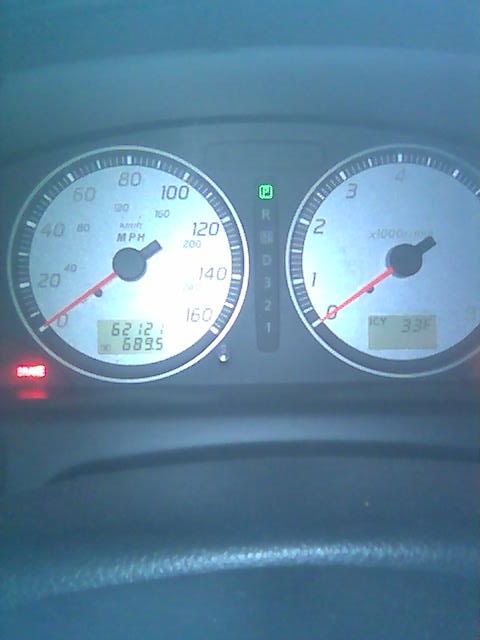
That is my cluster, BTW.
Speaking of which, would anyone like to donate some spare bulbs and sockets? I just need 6, the small(not 194) type that are like for the CEL, Brake, Washer Fluid lights. If anybody has a lot of spares they would like to donate, or sell for a decent price, let me know!
That is my cluster, BTW.
Speaking of which, would anyone like to donate some spare bulbs and sockets? I just need 6, the small(not 194) type that are like for the CEL, Brake, Washer Fluid lights. If anybody has a lot of spares they would like to donate, or sell for a decent price, let me know!
In after The Wizard.
MOHF, how can you say parts aren't an issue? That's the whole issue! Sockets, bulbs, wiring - all that is doable. Getting a PRND gauge cluster is the hard part. If I had a 4th gen over-seas gauge cluster with the PRND built in, I'd have done this a long time ago. What is your plan for the PRND21? Anyway, I'm behind you 100%, I just need to know how we are going to get the PRND letters/windows.
MOHF, how can you say parts aren't an issue? That's the whole issue! Sockets, bulbs, wiring - all that is doable. Getting a PRND gauge cluster is the hard part. If I had a 4th gen over-seas gauge cluster with the PRND built in, I'd have done this a long time ago. What is your plan for the PRND21? Anyway, I'm behind you 100%, I just need to know how we are going to get the PRND letters/windows.
The_Wizard, I thought it was you that had that. Nice job and thanks for the link. I might be doing that soon.


Yup, I35 cluster. But my car has the I35 ECU also, so it can display trip computer.
I30 is a similar cluster, but without trip computer and that one seems to have the same signals as the Gen 4 98+ Max's with digital odometer. Same goes for Gen 5 Maxima cluster.
If you are going to do so much modification and part hunting to get the stock A32 cluster to have PRND2L indication, you may as well install a newer cluster. It would be the same amount of work. And the I30/I35 fluorescent cluster looks so much sweeter than the basic Maxima cluster IMO

Newbie - Just Registered
Joined: May 2008
Posts: 2
I actuatly have this indicator in my 96. That's why I did a search and found this thread. My cluster looks just like the "leopard" cluster shown above. I pulled mine just to see if the bulbs were blown but they are all there, just no wiring ran to the plug. As far as I know my car is bone stock except for the wheels. I kinda wish it wasn't there, I hate for something to be there and not be functional.

 We'll begin figuring out the wiring next week when he gets back from vacation.

Last edited by Maxtank; May 21, 2008 at 06:37 PM.

I've thought about this a lot. Have some ideas in my head, but no time to work on it. I would use the shaft as the ground and make contact with something (like a spring) that is connected to a square cage that surrounds the shaft. (there would be 6, then in neutral have it show -- or 0). The shaft would most likely need to be a B&M since it's unpainted aluminum. Then use the ground signals to control a 7-segment display. Might have to break out my breadboard from college and try to at least get a proto working. Been 4-5 years since i've played with that stuff.
Your making this way harder than it needs to be, Back in my "crotchrocket" days (not too long ago but ended in a nasty crash) My friend had a digital gear indicator. It was after market and read engine rpm and speedo input and then calculated those 2 inputs to come up with which gear you were in. When it is first installed you ran the bike (why not a car) for a few seconds in each gear for it to calibrate itself. Worked flawlessly.

but that seems like a cool way to do it...
Maxtank,
You are making it harder than necessary.
Here is how I would go about it. Use the orange indicator in the shifter as a bridge for each connection. As it moves up and down along a pathway, have it disconnect one circuit, and connect another. Like this:
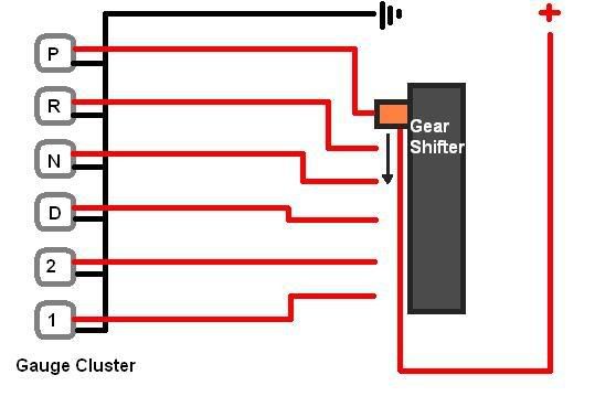
So as it moves from the P position, it breaks that circuit, turning off the bulb. Whatever gear it goes in next, the circuit would complete.
You are making it harder than necessary.
Here is how I would go about it. Use the orange indicator in the shifter as a bridge for each connection. As it moves up and down along a pathway, have it disconnect one circuit, and connect another. Like this:
So as it moves from the P position, it breaks that circuit, turning off the bulb. Whatever gear it goes in next, the circuit would complete.

5 Spds dont have that....
Maxtank,
You are making it harder than necessary.
Here is how I would go about it. Use the orange indicator in the shifter as a bridge for each connection. As it moves up and down along a pathway, have it disconnect one circuit, and connect another. Like this:
So as it moves from the P position, it breaks that circuit, turning off the bulb. Whatever gear it goes in next, the circuit would complete.
In which case, I have absolutely no idea. You could apply the same idea to the 5spd, each gate(gear) would have its own circuit terminal, using the shaft as the switch. Like you said. I guess I didnt understand that you were a 5spd going for this. Haha.
There isnt a wire on the TCU or ECU for gear indicator?
There isnt a wire on the TCU or ECU for gear indicator?
Technically... for the 5-spd indicator you could use WOT switches some people use to disable their automatic drop resistor when you floor it. You could have something along the lines of that, physically setup inside your shifter rod box. Have one setup for each gear; putting it in gear will push the switch down sending an electrical current to the Gauge cluster.
Technically... for the 5-spd indicator you could use WOT switches some people use to disable their automatic drop resistor when you floor it. You could have something along the lines of that, physically setup inside your shifter rod box. Have one setup for each gear; putting it in gear will push the switch down sending an electrical current to the Gauge cluster.
