
Mystery Part - "white box" under dash
 08-24-2008, 01:49 AM
#1

Mystery Part - "white box" under dash
About 2 years ago I busted a little white box under the dash (rolled over on it while working under the dash) and I was consumed with what I was doing and it didnt seem to bother anything so I chunked it into the moutain of other screwed up parts. I've since been unable to find it and I badly want to replace it now. It was located behind the bottom panel under the steering wheel, I think 
Only things I have noticed that arent working due to that box is the light ring around the key, auto on dome light, and possibly the door chime. I might have removed the chime myself becuase chimes sound gay.. but I dont remember it was so long ago and chimes are the first thing I remove from my rides.
I've searched and searched for that stupid little box because I want my light ring back and my auto on dome but I dont know exactly what to call the sucker.
Anyone with a proper name for that "white box" or a part number will be my new hero


 08-24-2008, 10:22 AM
#4
Yeah, pretty common part for people to unplug because they hate the chiming. Personally I feel like it's there for a reason. It's saved me many times from leaving my keys in the ignition.


 08-24-2008, 01:52 PM
#7
Thanks for your help but I am now left with the question as to why my light ring around the key and the auto feature on the dome light dont work. Of course I checked the bulbs.. not the issue. I figured those might be tied in with that box in some way.
08-24-2008, 02:08 PM
#9
Put any LEDs in your window switches lately?
08-24-2008, 03:59 PM
#10
 nor do mine....
08-24-2008, 04:41 PM
nor do mine....
08-24-2008, 04:41 PM
#12
No window switches yet.. waiting on SMT's and resistors. I do however have a LED in my dimmer control switch, security light, cluster and the gear selector. I while back I tried to hook up an LED into the Cruise switch and now my switch isnt working.. got to order another one. You think the LED's or the broken cruise switch could be to blame? Those lights went out the same time I broke the chime box and started modding with LED's.
08-24-2008, 04:46 PM
#13
Yours not working either ehh  Have you tried connecting the chime to see if they start working.. some say the box isnt the issue but the box on my 99 didnt just have a chime it, also had a small board of electrical goodies in there and the board snapped in half.. part of the reason I chunked it.
Have you tried connecting the chime to see if they start working.. some say the box isnt the issue but the box on my 99 didnt just have a chime it, also had a small board of electrical goodies in there and the board snapped in half.. part of the reason I chunked it.
09-07-2008, 12:38 PM
#14
cruise control led
Does anyone know the polarity + and - terminals looking at the switch when its apart? There are 2 bulbs in there and looking at the switch the terminal are left to right. How about dimmer switch ? Dimmer switch has the terminals up and down like the harzard switch. looking on putting leds in there.
Last edited by maxprivate; 09-07-2008 at 12:41 PM.
 09-07-2008, 05:07 PM
#16
Does anyone know the polarity + and - terminals looking at the switch when its apart? There are 2 bulbs in there and looking at the switch the terminal are left to right. How about dimmer switch ? Dimmer switch has the terminals up and down like the harzard switch. looking on putting leds in there.
Last edited by pmohr; 09-07-2008 at 05:10 PM.
09-07-2008, 05:25 PM
#17
I saw your original post.. and instead of trying to be a sm@rt @ss you should think of something positive to say. If you look into this thread someone mentioned earlier they put leds in their cruise control switch , which is the reason I posted my question.
09-07-2008, 05:29 PM
#18
When you checked the switches with a multimeter, could you not figure out which lead was positive and which was negative?
Of course, you did try that, right?
Besides, this thread is not about putting LEDs in switches, it's about diagnosing a different problem. You've got more than enough posts to start a new thread with your question.
09-07-2008, 05:36 PM
#19
I have something very useful to say.
When you checked the switches with a multimeter, could you not figure out which lead was positive and which was negative?
Of course, you did try that, right?
Besides, this thread is not about putting LEDs in switches, it's about diagnosing a different problem. You've got more than enough posts to start a new thread with your question.
") anyhow how can you determine which is negative on the copper terminals with no power applied to it? I don't think you can unless you know something I don't. I have the switches in my house and was hoping someone that has done it would know off hand. Besides I don't feel the need to start a new thread when I can search and ask questions. I know many have done this before.
09-08-2008, 03:21 AM
anyhow how can you determine which is negative on the copper terminals with no power applied to it? I don't think you can unless you know something I don't. I have the switches in my house and was hoping someone that has done it would know off hand. Besides I don't feel the need to start a new thread when I can search and ask questions. I know many have done this before.
09-08-2008, 03:21 AM
#21
Likewise, checking continuity to the connector pin where the switch receives power?
09-08-2008, 03:30 AM
#22
This is exactly what I'll do. I'll just check the connector pin for neg and pos. I was just trying to see if I can get an answer without having to go to the car. Thanks for the help though.
09-08-2008, 03:34 AM
#23
No need to go to the car, just take a look through EL and it'll show you what pins are power and ground.
09-08-2008, 04:06 AM
#24
what do you mean by el? looking (facing it) at the switch with it all apart there are 2 bulbs left to right. so I need to know if left copper terminal is neg or pos for the ON light green. and right side bulb (criuse control light) which is neg , pos copper terminal.
09-08-2008, 04:38 AM
#25
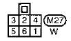
Ground for the CRUISE light should be pin 4, and power comes in through pin 2.
For the ON light, pin 6 should be power, pin 5 should be ground.
Check continuity to the solder pads to those pins, should tell you which is which.
The pins aren't labeled how you'd think (FTR, I don't know if that's harness side or ASCD switch side, I'm leaning towards the latter):
Last edited by pmohr; 09-08-2008 at 04:41 AM.
09-08-2008, 04:46 AM
#26
FSM (see sig). EL is the electrical section.
Ground for the CRUISE light should be pin 4, and power comes in through pin 2.
For the ON light, pin 6 should be power, pin 5 should be ground.
Check continuity to the solder pads to those pins, should tell you which is which.
The pins aren't labeled how you'd think (FTR, I don't know if that's harness side or ASCD switch side, I'm leaning towards the latter):
09-08-2008, 01:47 PM
#27
FSM (see sig). EL is the electrical section.
Ground for the CRUISE light should be pin 4, and power comes in through pin 2.
For the ON light, pin 6 should be power, pin 5 should be ground.
Check continuity to the solder pads to those pins, should tell you which is which.
The pins aren't labeled how you'd think (FTR, I don't know if that's harness side or ASCD switch side, I'm leaning towards the latter):
Ground for the CRUISE light should be pin 4, and power comes in through pin 2.
For the ON light, pin 6 should be power, pin 5 should be ground.
Check continuity to the solder pads to those pins, should tell you which is which.
The pins aren't labeled how you'd think (FTR, I don't know if that's harness side or ASCD switch side, I'm leaning towards the latter):
09-08-2008, 05:34 PM
#28
I checked it out and determined that the copper terminals on the left side was positive (LOOKING AT THE SWITCH) and I was wrong  the leds didn't work. I checked voltage at the plug and the top 1 and 2 terminal have power all the time. This must be for the cruise control light. So I guess how this works is that the white piece inside the switch slides to the ON position if you call for cruise control and the ON light will illuminate. The white plastic piece with three copper stripes moves along the copper strip path always providing a ground for the cruise control light to have power all the time providing lights are on.
But looking at the switch and checking for power at the plug doesn't really help me figure which is negative.And the diagram doesn't match what the actual power at the plug when I checked with my meter. I guess I'll just try swaping the led the other way and it should work. Figuring out the dimmer switch led was easy. Top is negative and bottom is positive. Soldered the led in place and it worked beautifully. So thats 1 out of 2. I'll try the ccs again tomorrow.
the leds didn't work. I checked voltage at the plug and the top 1 and 2 terminal have power all the time. This must be for the cruise control light. So I guess how this works is that the white piece inside the switch slides to the ON position if you call for cruise control and the ON light will illuminate. The white plastic piece with three copper stripes moves along the copper strip path always providing a ground for the cruise control light to have power all the time providing lights are on. But looking at the switch and checking for power at the plug doesn't really help me figure which is negative.And the diagram doesn't match what the actual power at the plug when I checked with my meter. I guess I'll just try swaping the led the other way and it should work. Figuring out the dimmer switch led was easy. Top is negative and bottom is positive. Soldered the led in place and it worked beautifully. So thats 1 out of 2. I'll try the ccs again tomorrow.

Thread
Thread Starter
Forum
Replies
Last Post