
View Poll Results: 5th Gen LED mod thread, Yepe or Nepe?
I'd read it, maybe even subscribe to it, but I'd never actually have the balls to do it on my car


15.22%


I've already done it, but would like to contribute my experience and technique to this thread


15.22%
Voters: 46. You may not vote on this poll
How to LED your 5th gen _~ Feeler thread .w. POLL

Likely chance it wouldn't, but electrical is a wild and crazy thing, and if there's something weird going on in the LED then the ground circuit of the components could be effected. The power side is completely separate from the rest of the gauges, but the ground is common IIRC.
It's unlikely, but it just makes good sense to remove the thing you changed when you have an issue after a modification.
Until some of the tests are done that I"ve recommended I can't guess much more
It's unlikely, but it just makes good sense to remove the thing you changed when you have an issue after a modification.
Until some of the tests are done that I"ve recommended I can't guess much more

i did notice one thing if they are sharing a common ground this could be a problem standard bulbs are not polorized where these led's have diode to block reverse flow on the ground side wouldnt this cause a issue such as current surge as the diode clamps the flow on the ground plane??
i did notice one thing if they are sharing a common ground this could be a problem standard bulbs are not polorized where these led's have diode to block reverse flow on the ground side wouldnt this cause a issue such as current surge as the diode clamps the flow on the ground plane??

If they have an extra diode it's harmless to the function of the gauges. The illumination + circuit only has power when it's on, so it can't trickle into the ground side like the dome lights do when LED's are installed.
For the time being, you're just overthinking this, spend this time physically checking and we can start moving forward to getting your gauges fixed.

Member

Joined: May 2011
Posts: 72
From: Suffolk, Long Island
Cjandura, if you dont try that out today, ill try it tomorrow morning.
Also, Tuner you think this could have anything to do with the socket I used in the one spot? After I broke the one socket, I used the "brights" socket from in between the blinkers. It was a brownish color instead of the black. I dont know if there is any difference but I would consider it another factor?
Also, Tuner you think this could have anything to do with the socket I used in the one spot? After I broke the one socket, I used the "brights" socket from in between the blinkers. It was a brownish color instead of the black. I dont know if there is any difference but I would consider it another factor?
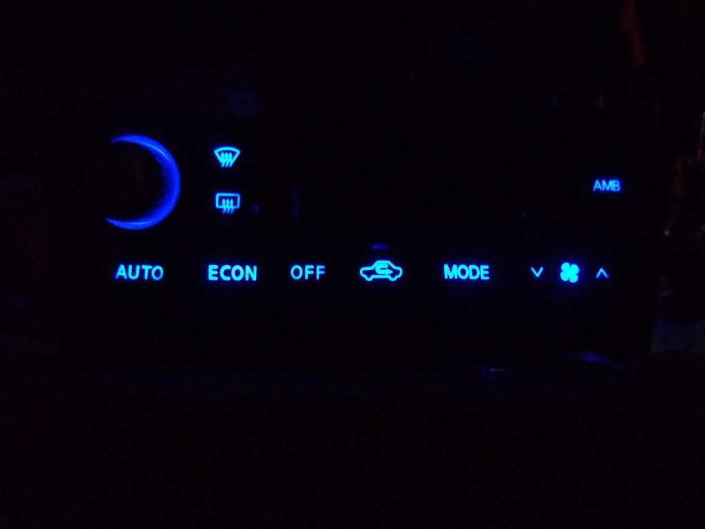
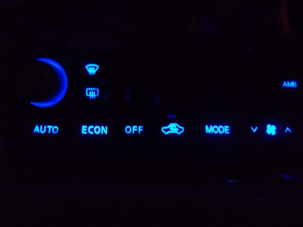
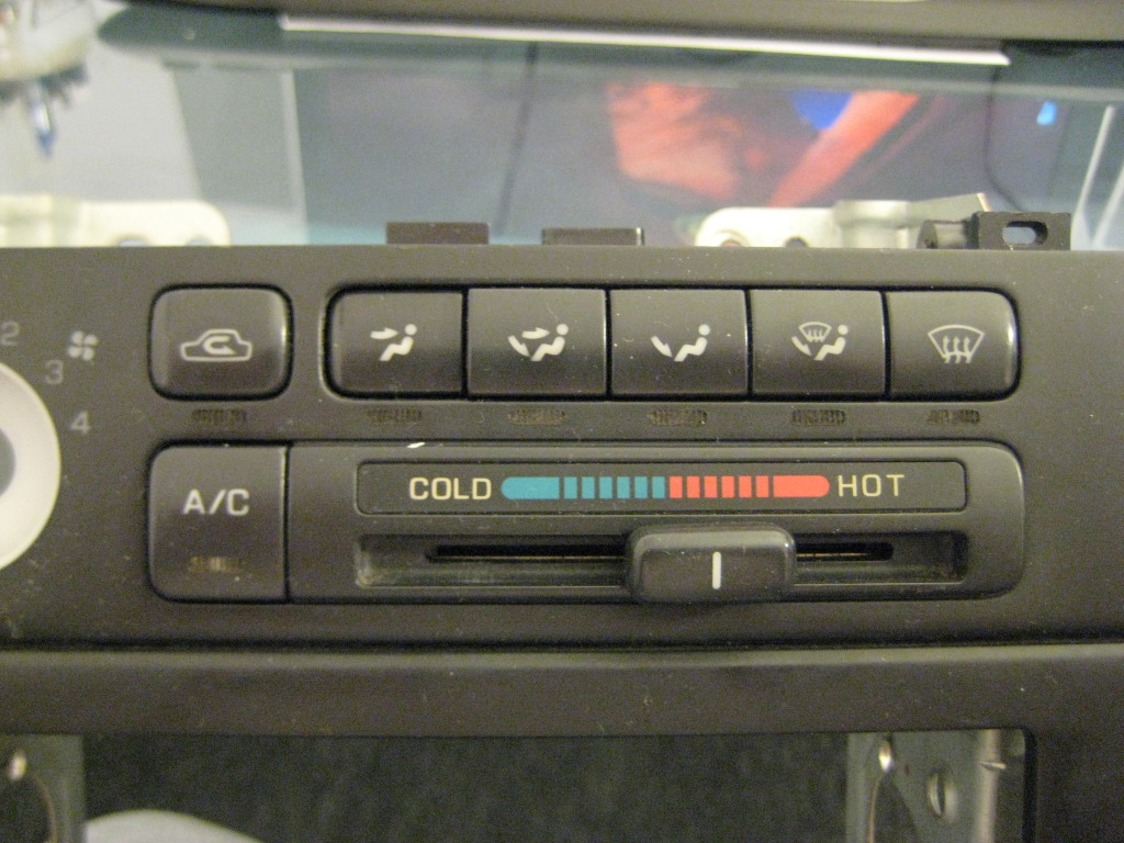
NO HOTSPOT CLIMATE CONTROL~ ONLY 3 LED's In Stock Locations
Very large shout out to Shinjiduo, he is the one you all want to thank for this. His suggestion to use the 360 degree LED's from SuperBrightLEDs.com is what brought this to fruition. I had no idea these little beauties were out on the market, let alone so bloody awesome.
Enough chatter, here we go:
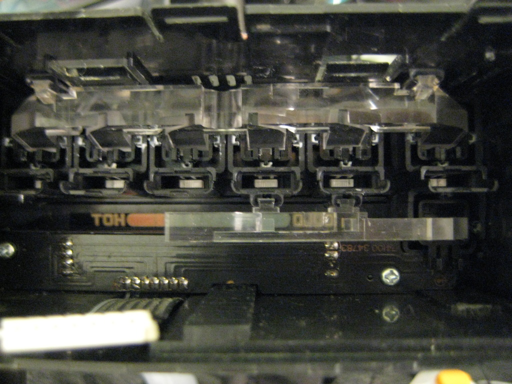
Your Climate Control unit ready for bulb removal:
Removing stock bulbs:
Now use a small screwdriver to slide the contact wires off their 'hooks' on the base:
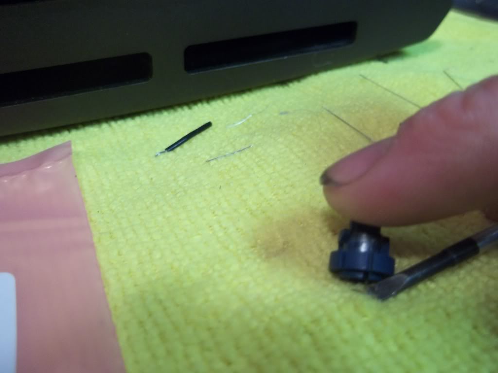
Contacts off 'hooks/mounts' and bulb ready for removal:
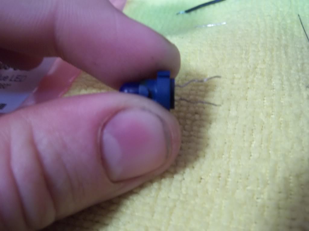
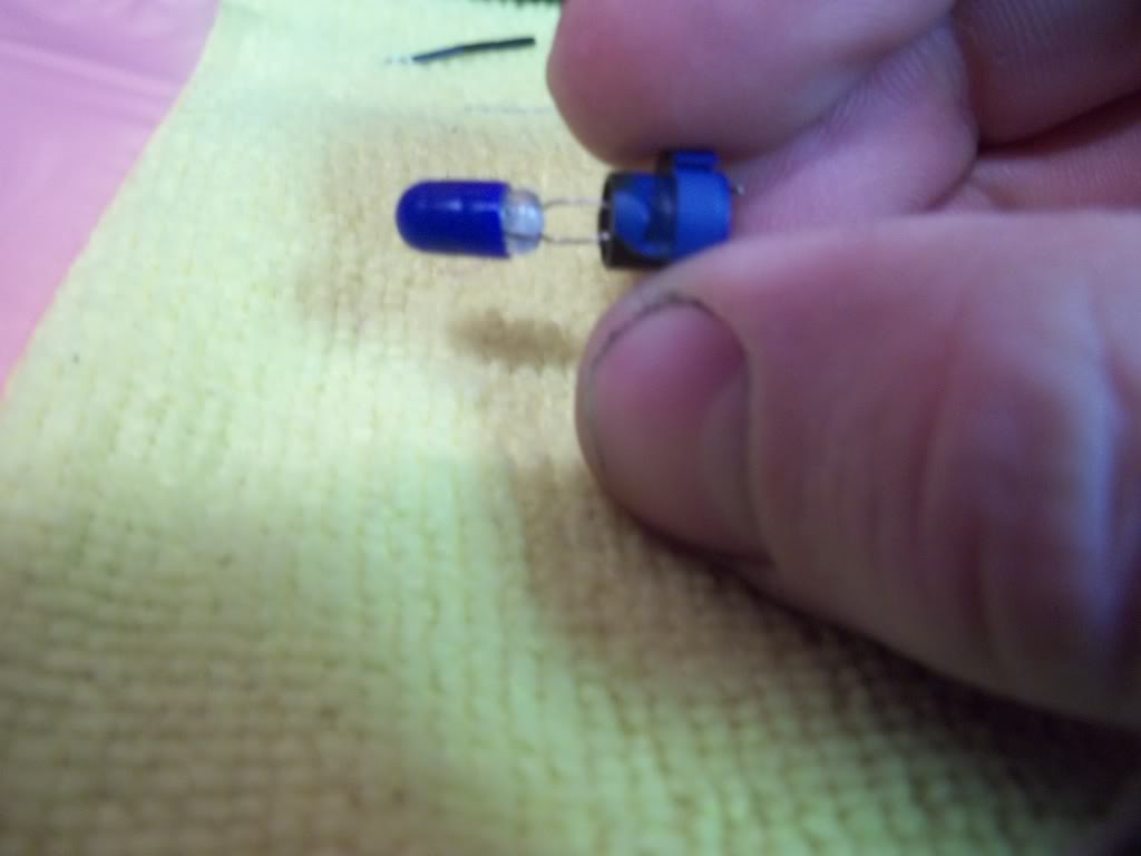
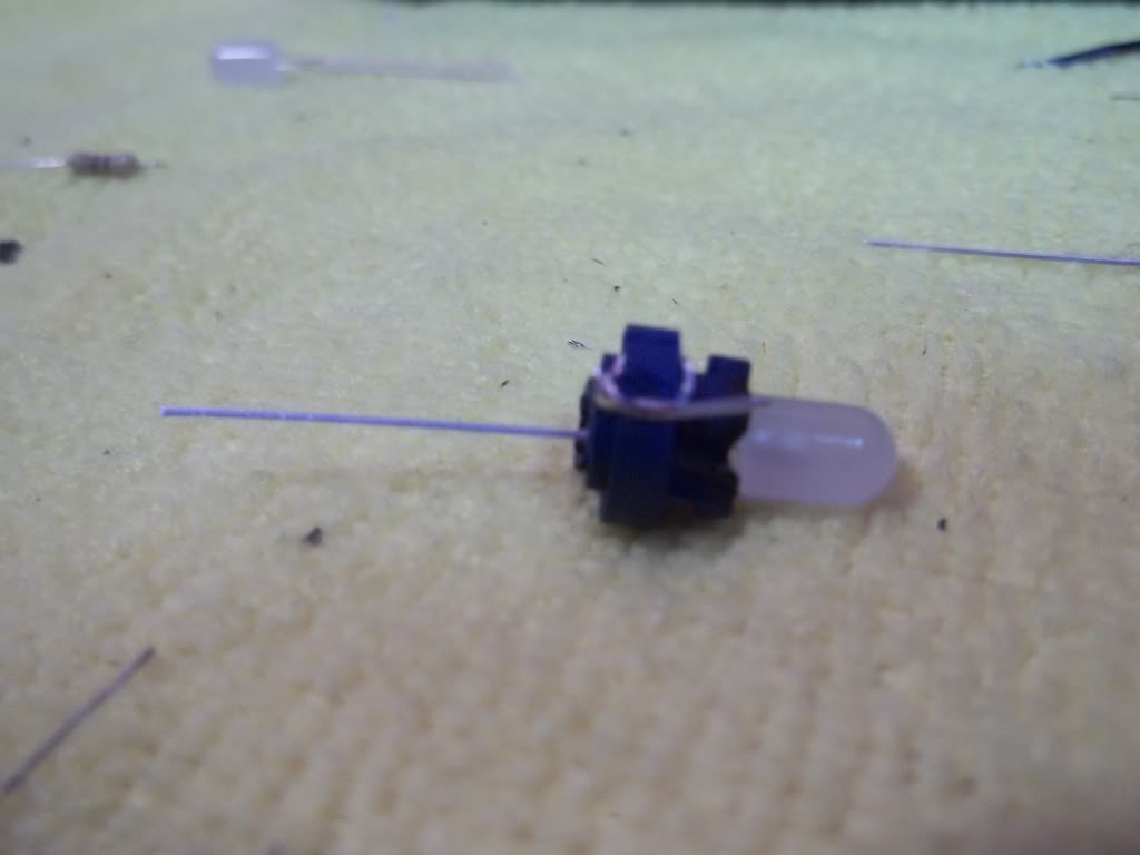
Prepping your LED for install. You'll need 3 of these 5mm 360 Degree LED's, in whatever colour you want to do. Mine are blue. And 3 resistors, either 470k or 560k ohm, 1/4 watt.

It doesn't matter which end you put the diode on, you don't even need to worry about positive/negative leads for this application.
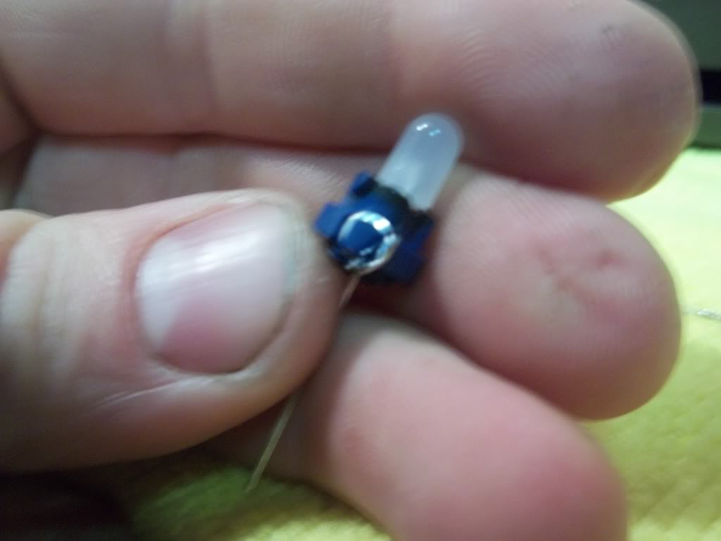
Just stuff the LED in there and wrap one lead around the 'hook' just like the stock one was.
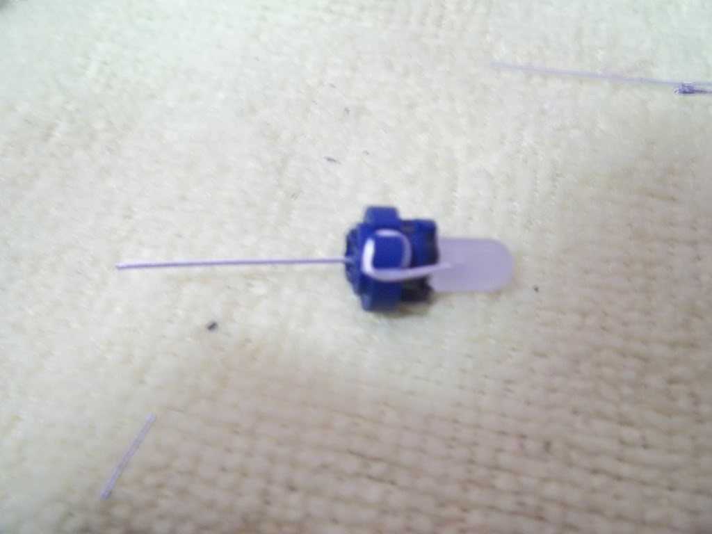
I put a little dab of solder to hold it indefinately, just make sure you do it on the back side (opposite the LED), or it will interfere with the mounting. Then cut off the excess contact.
Now pre-tin your resistor lead on one end and solder it to the other lead on the LED you just installed:
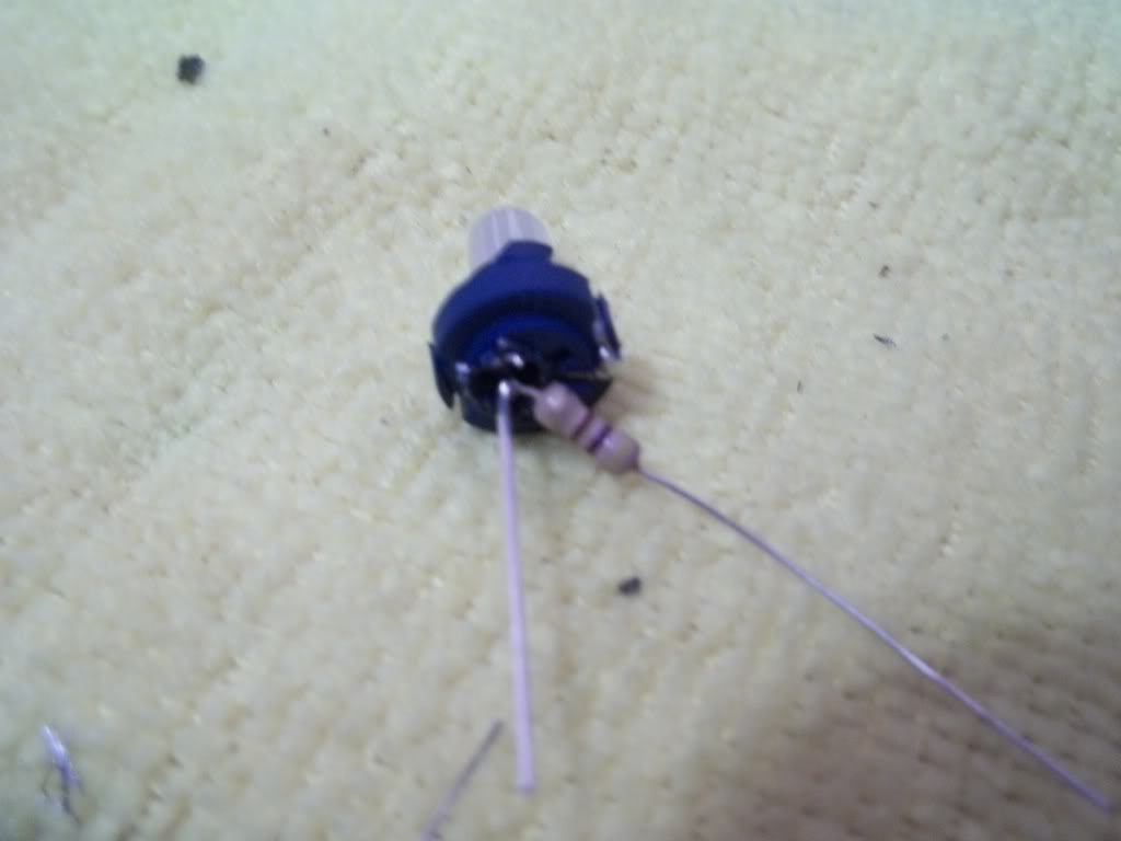
Cut off excess wire:

Enough chatter, here we go:
Your Climate Control unit ready for bulb removal:
Removing stock bulbs:
Now use a small screwdriver to slide the contact wires off their 'hooks' on the base:
Contacts off 'hooks/mounts' and bulb ready for removal:
Prepping your LED for install. You'll need 3 of these 5mm 360 Degree LED's, in whatever colour you want to do. Mine are blue. And 3 resistors, either 470k or 560k ohm, 1/4 watt.
It doesn't matter which end you put the diode on, you don't even need to worry about positive/negative leads for this application.
Just stuff the LED in there and wrap one lead around the 'hook' just like the stock one was.
I put a little dab of solder to hold it indefinately, just make sure you do it on the back side (opposite the LED), or it will interfere with the mounting. Then cut off the excess contact.
Now pre-tin your resistor lead on one end and solder it to the other lead on the LED you just installed:
Cut off excess wire:
Wrap this lead around the other 'hook' on the base. Same deal.
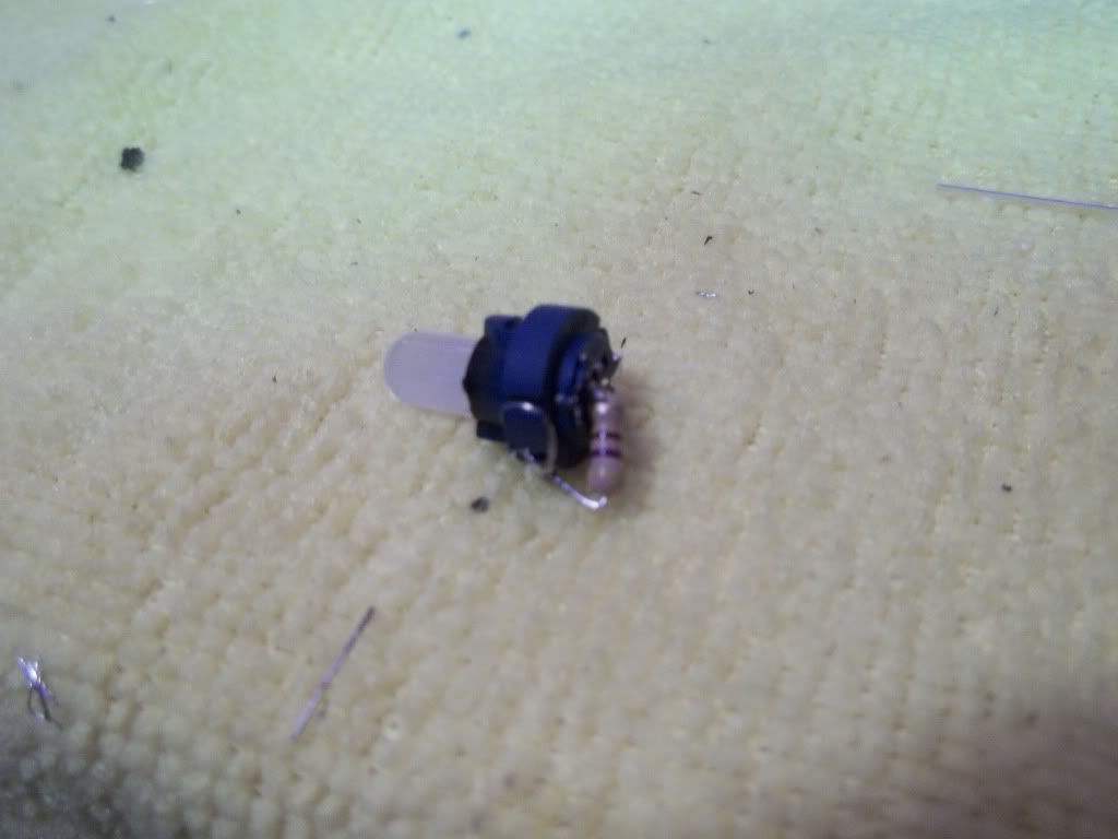
Install
Now for the beauty part, I was VERY surprised that there was actually no hotspots, I NEVER expected this level of even distribution.
If there's enough interest, Either Shinjiduo or I could make a batch of these up and sell them as "DROP IN" units. Price would be a little high from me, Feel free to PM Shinjiduo he loves to make money and may do it cheaper
-Matt

^^This looks pretty good, I have hotspots with the drop-ins I purchased from superbrightleds, the widest beam they had was 120 I believe for the twist n lock. This doesn't look that difficult either. great pics too
Hey Tuner what you think i could do with some cool white 4w 6000k single chip 12v spotlights made for the home?? there $2.50 at walmart on clearance made by LG ?maby some high power LED reverse lights?

Just make sure to keep those bad boys away from the plastic, and make sure there's ample air flow within the light prior to install. I'd be nervous about them in the Maxima's reverse lights because there's not much room. Run them overnight and see how hot they get and go from there.
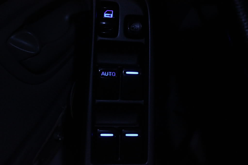
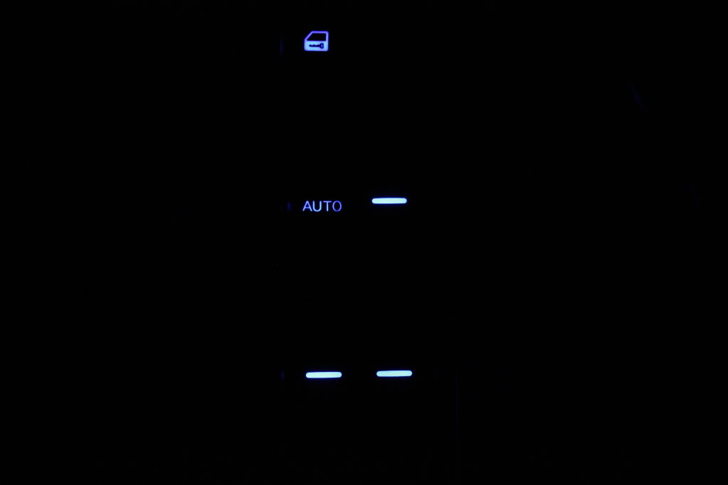
How to LED your Master switch.
This info is kind of a guideline, because Nissan decided to switch the Master switch layout a few times throughout the 5th gen. The one I did is the most common in my experience, and in either regard, this should point you in the right direction.
Master switch:
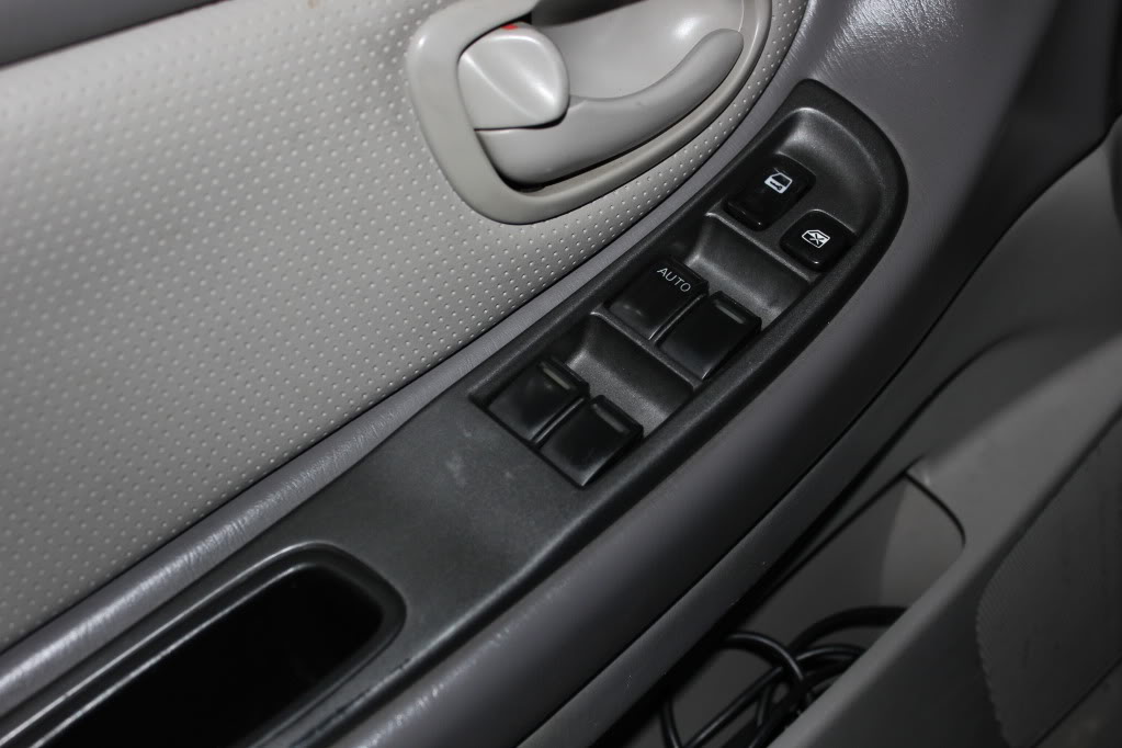
Pop the cap off the screw head inside the inner door handle:
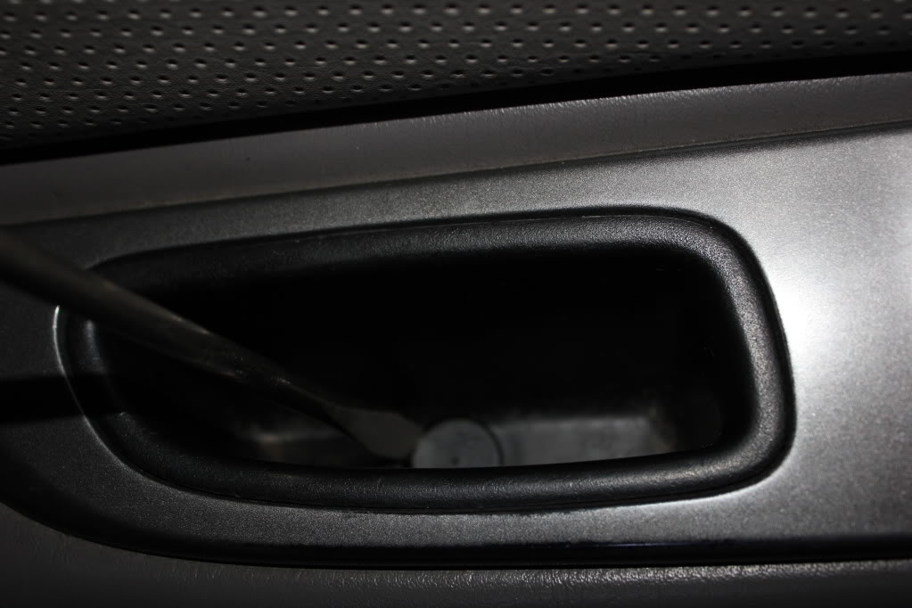
Remove screw, phillips (star) head:
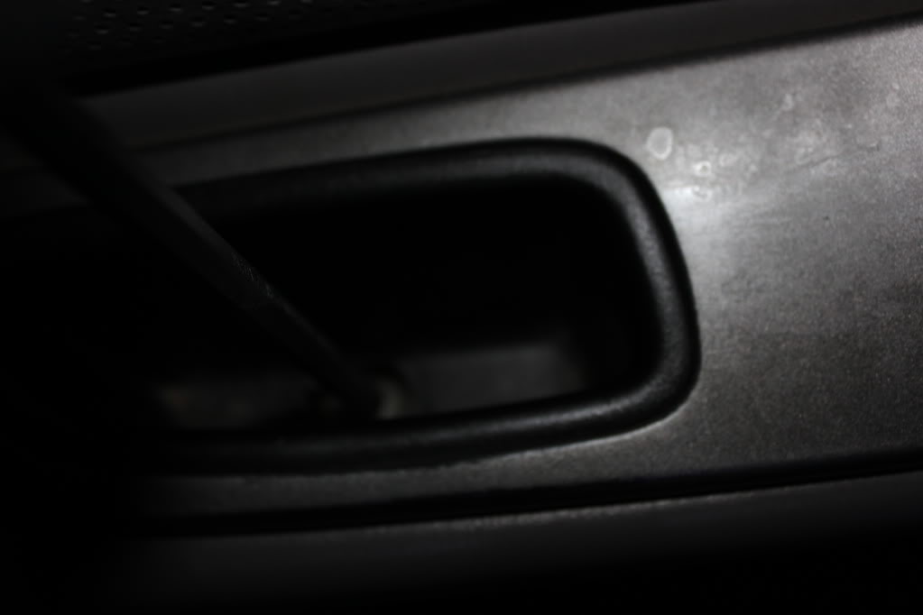
Now pry a little under the back end and it will start coming up, lift from the back and then pull toward you:
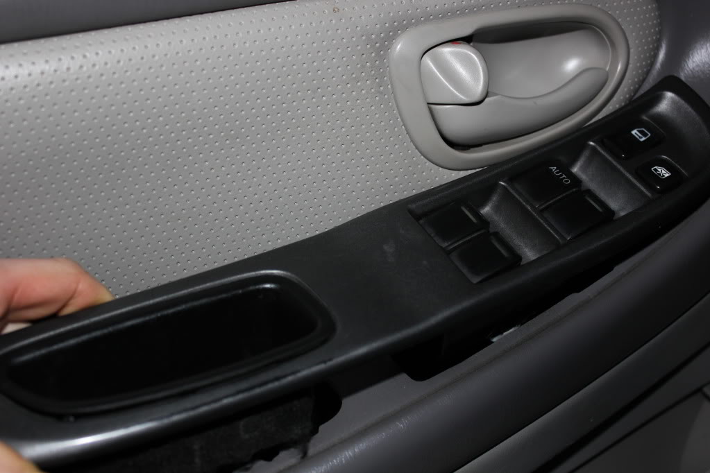
Disconnect the harnesses:
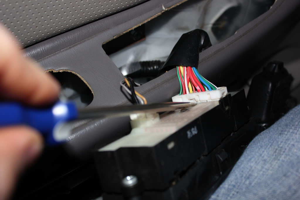

Now you can pry out the white piece, this is the main switch assembly that you want, the buttons can stay with the trim piece. There's 4 tabs, work your way back and forth gently until the white piece starts coming out. (enter pun here)
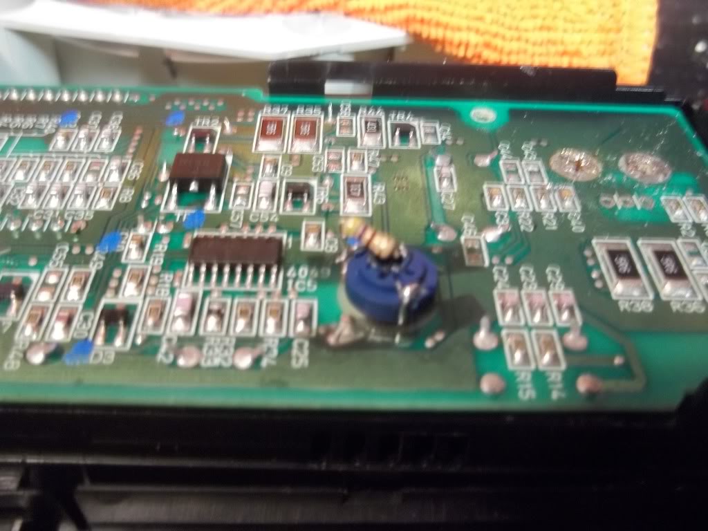
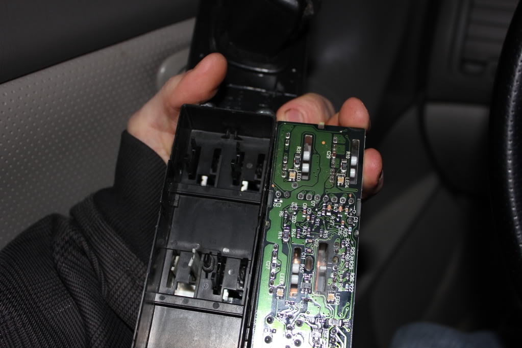
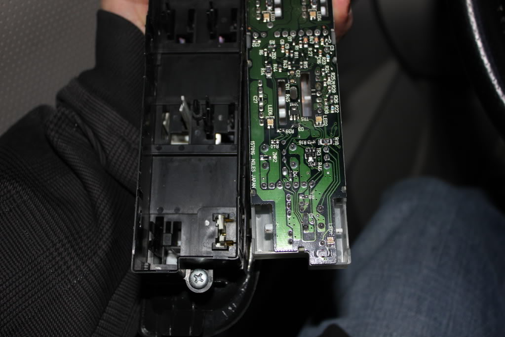
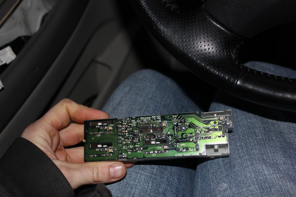
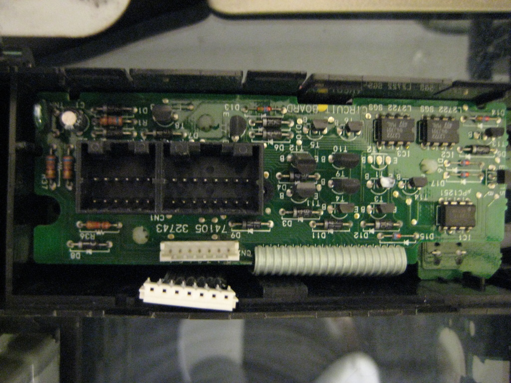
This is the circuit board side you'll be dealing with:
This info is kind of a guideline, because Nissan decided to switch the Master switch layout a few times throughout the 5th gen. The one I did is the most common in my experience, and in either regard, this should point you in the right direction.
Master switch:
Pop the cap off the screw head inside the inner door handle:
Remove screw, phillips (star) head:
Now pry a little under the back end and it will start coming up, lift from the back and then pull toward you:
Disconnect the harnesses:
Now you can pry out the white piece, this is the main switch assembly that you want, the buttons can stay with the trim piece. There's 4 tabs, work your way back and forth gently until the white piece starts coming out. (enter pun here)
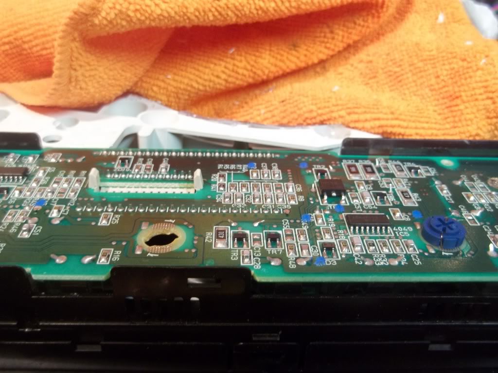
This is the circuit board side you'll be dealing with:
Last edited by TunerMaxima3000; Feb 20, 2012 at 07:06 PM.
Now wander inside with this piece. Get your soldering guy warmed up and your parts ready.
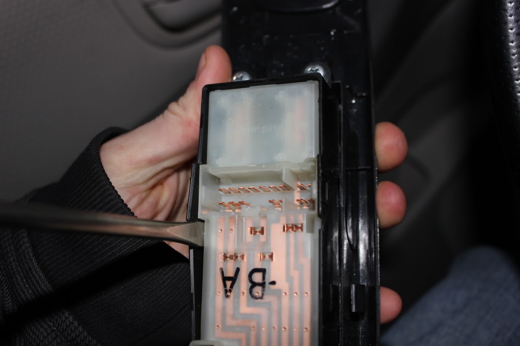
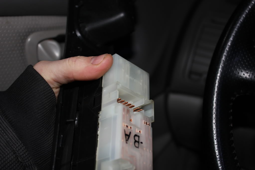
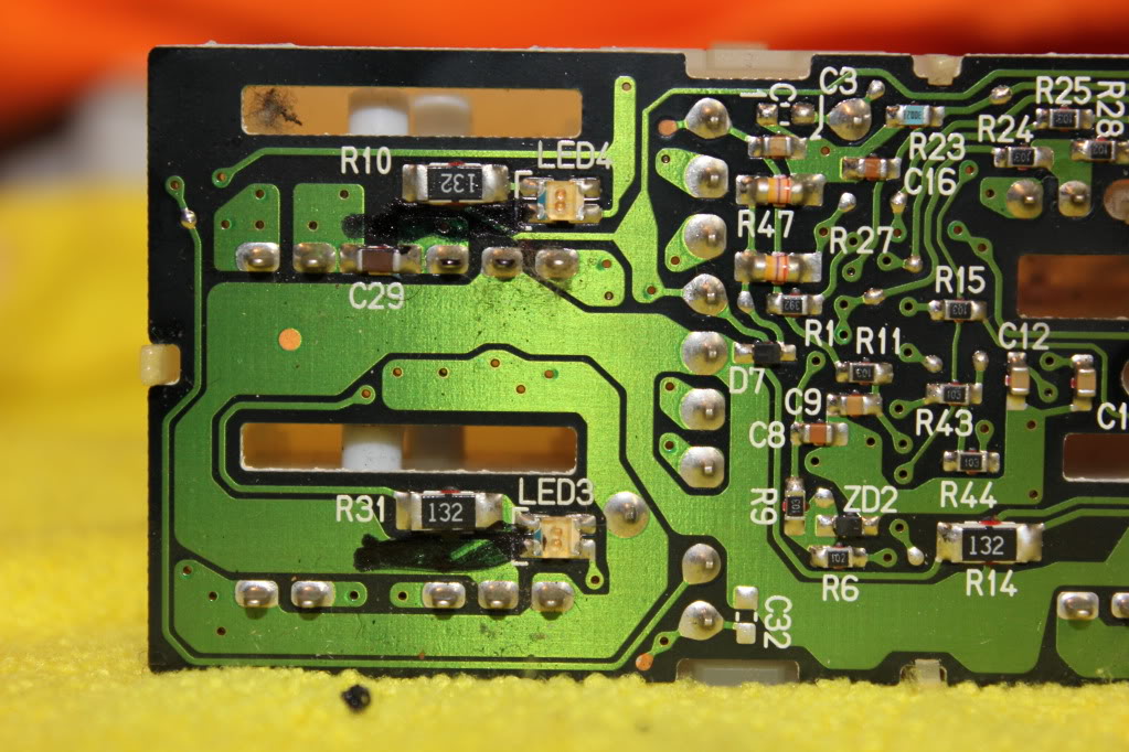
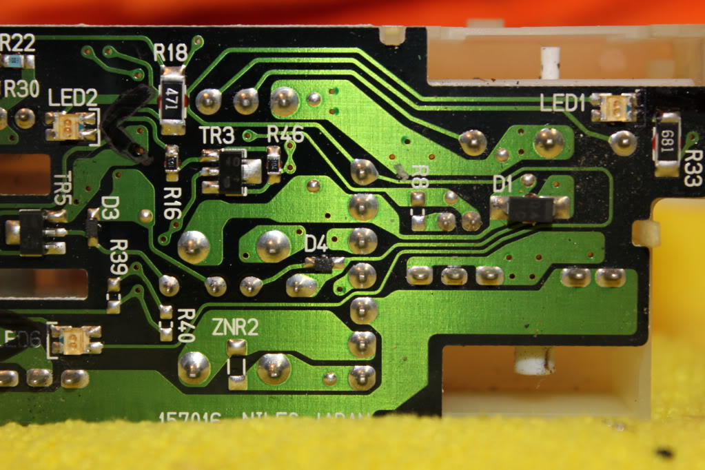
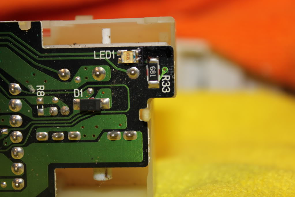
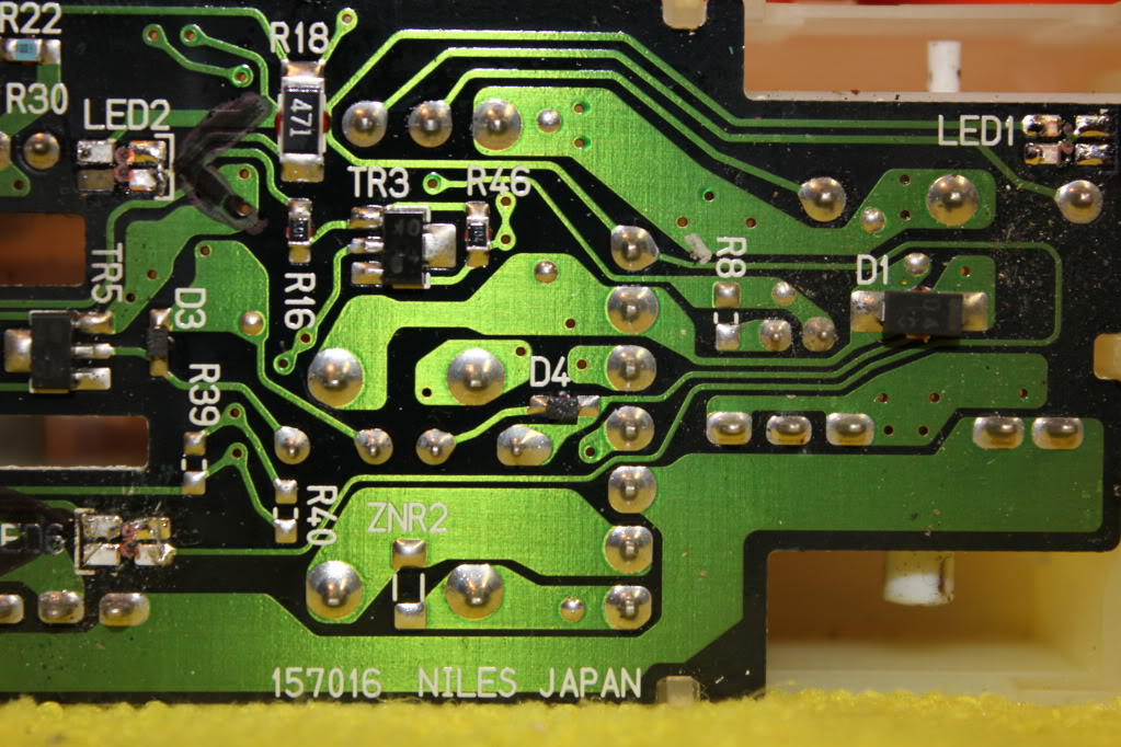
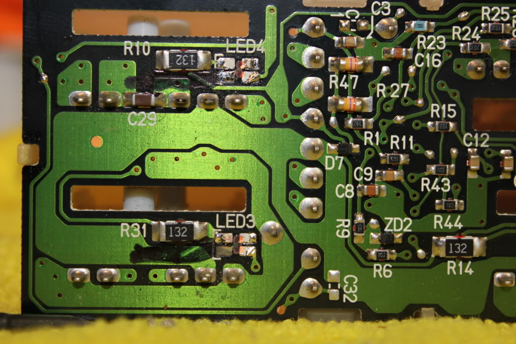
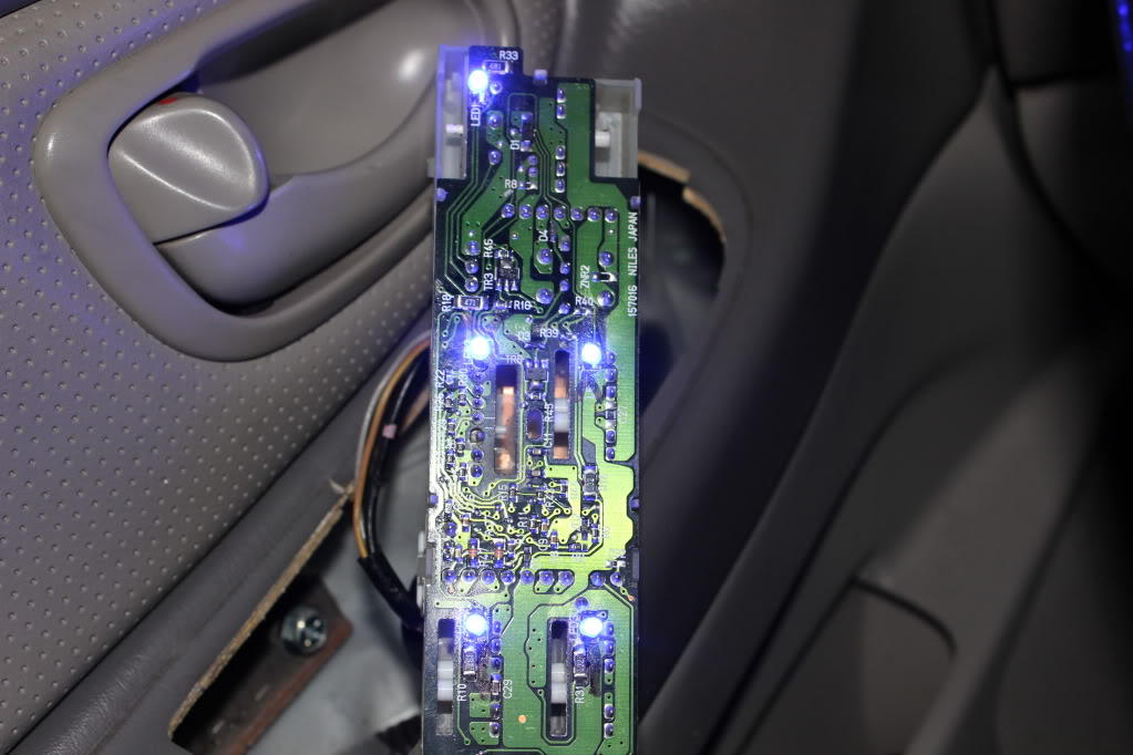
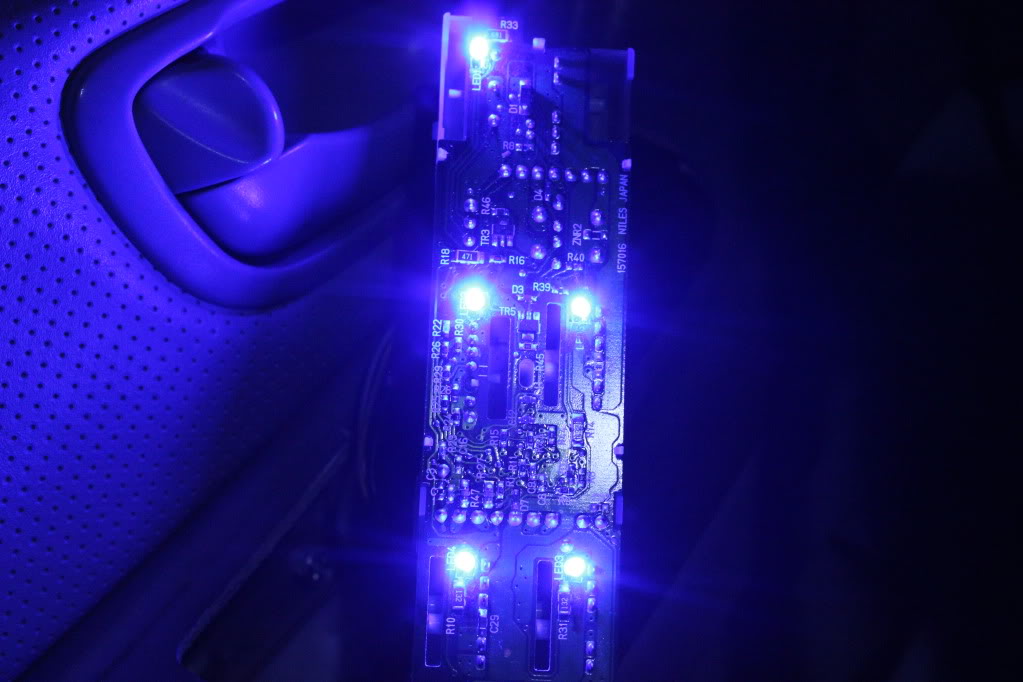
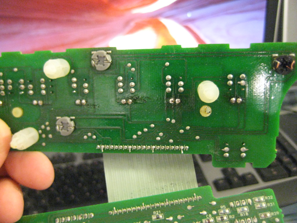
Here are some pictures of the stock board. The Left side of the pictures is the REAR of the switch, for reference:

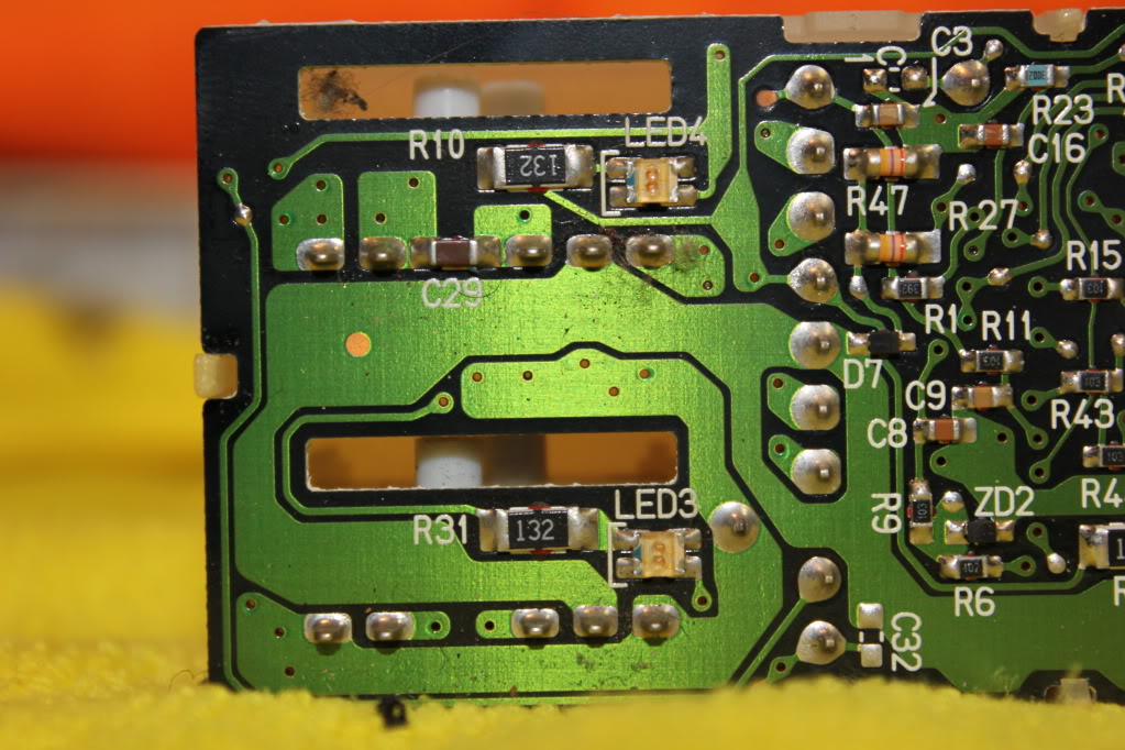
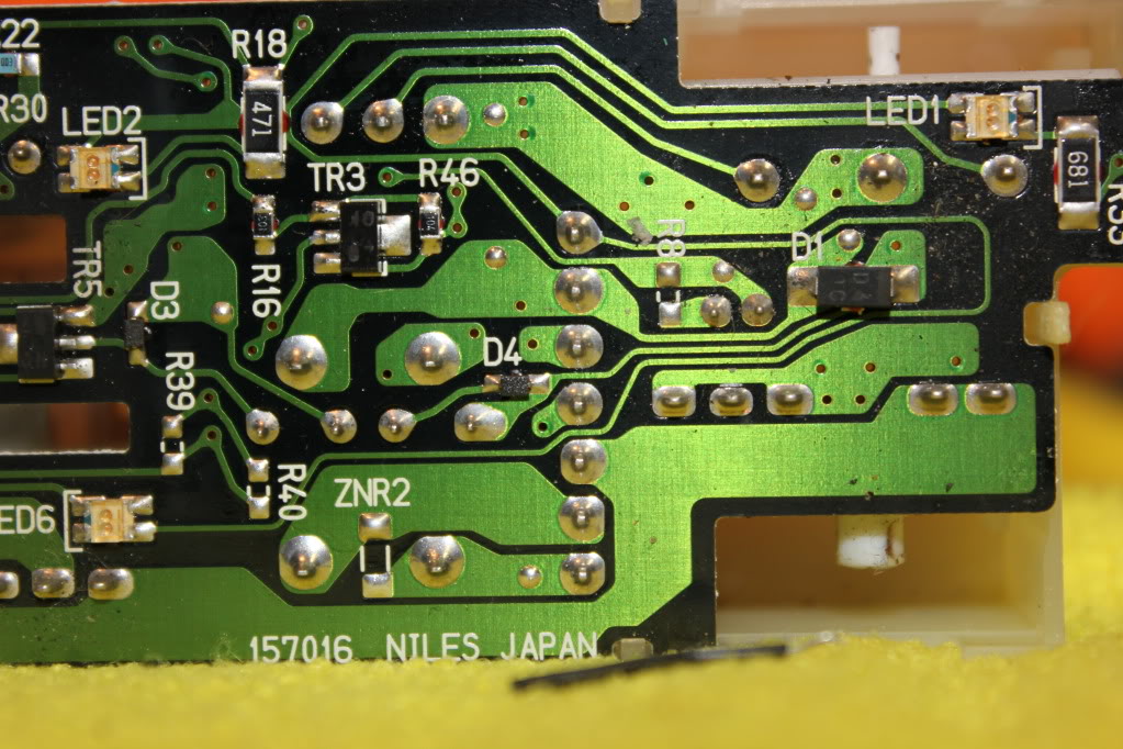
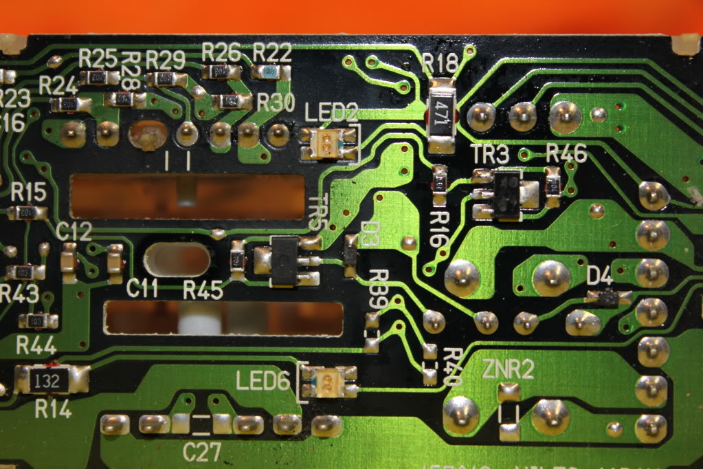
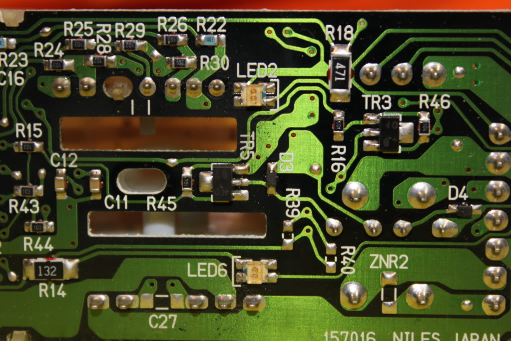
Now looking at these pictures you can see that one side of each "SMD" (Surface Mount Diode [led]) is marked with an identifier. In our case on this particular board, I know it's the negative side. However, because there's no guarantees that your board will be the same, do the following:
Mark these indicators ON THE CIRCUIT BOARD clearly. I use a pernament marker:
Here are some pictures of the stock board. The Left side of the pictures is the REAR of the switch, for reference:
Now looking at these pictures you can see that one side of each "SMD" (Surface Mount Diode [led]) is marked with an identifier. In our case on this particular board, I know it's the negative side. However, because there's no guarantees that your board will be the same, do the following:
Mark these indicators ON THE CIRCUIT BOARD clearly. I use a pernament marker:
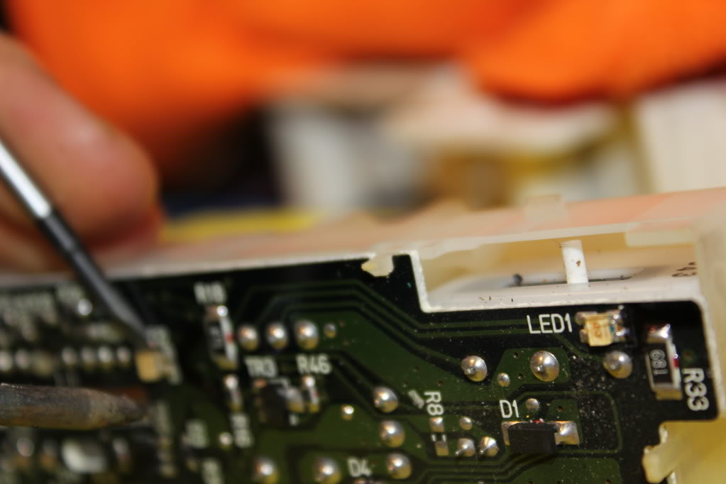
Now, I hate the 5th gen SMD's. They're REALLY, REALLY on there. It's a huge PITA to get them off. Just be very sure not to overheat the circuit board. If you've been at them too long, just start on another one and come back.
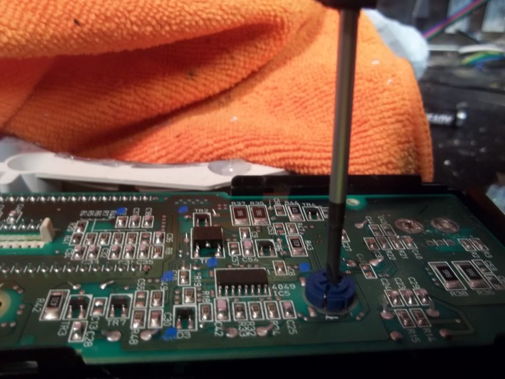
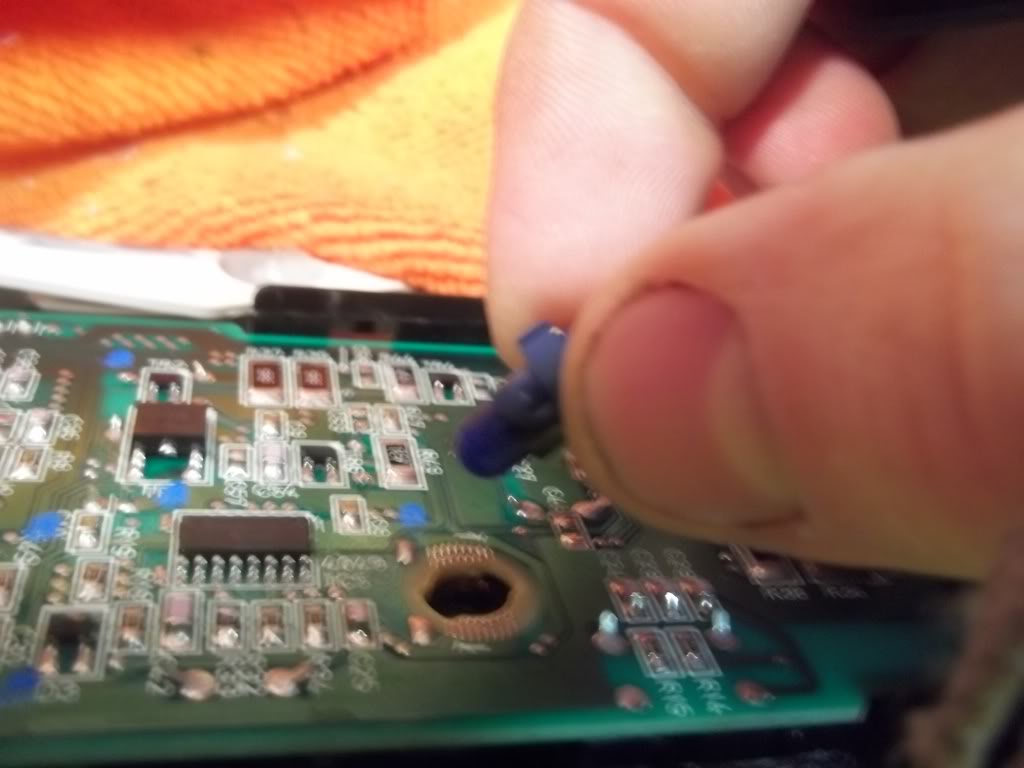
The best thing to do is use solder wick or a solder sucker to remove all the solder you can get off the mounting contacts (4 points on each SMD)
Then I find for these, standing the whole assembly on it's side, and then using a precision flathead screwdriver to push down on the side of the SMD while heating one side, then the other, back and forth and back and forth is the easiest way to smoothly remove them.
If someone has some awesome easier way please inform. Here's a couple snaps of that process, and the SMD's Removed:


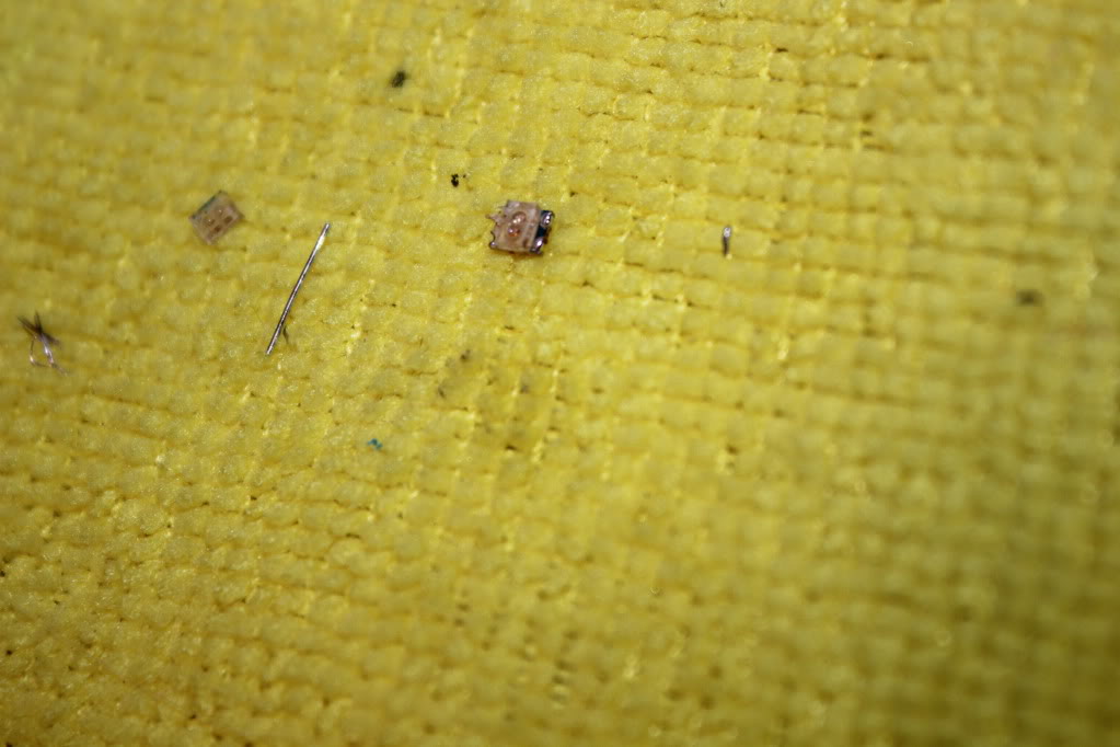
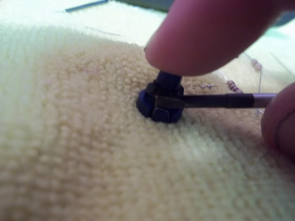
Now to verify which side is positive and which is negative, grab one of the SMD's you took off, don't be surprised if a few of them are broken and don't work.
Grab a 470/560k resistor and hook 12V+ to one end of the SMD you took off, and 12V- to the other end. If it doesn't work reverse them. Once it lights up, note which one is power, and which one is negative. In this case, my NEGATIVE 12V- lead is on the little indicator on the SMD, which tells me that all my markings on the circuit board are NEGATIVE. Obviously then, opposite the NEGATIVE marks are my POSITIVE contacts.
The best thing to do is use solder wick or a solder sucker to remove all the solder you can get off the mounting contacts (4 points on each SMD)
Then I find for these, standing the whole assembly on it's side, and then using a precision flathead screwdriver to push down on the side of the SMD while heating one side, then the other, back and forth and back and forth is the easiest way to smoothly remove them.
If someone has some awesome easier way please inform. Here's a couple snaps of that process, and the SMD's Removed:
Now to verify which side is positive and which is negative, grab one of the SMD's you took off, don't be surprised if a few of them are broken and don't work.
Grab a 470/560k resistor and hook 12V+ to one end of the SMD you took off, and 12V- to the other end. If it doesn't work reverse them. Once it lights up, note which one is power, and which one is negative. In this case, my NEGATIVE 12V- lead is on the little indicator on the SMD, which tells me that all my markings on the circuit board are NEGATIVE. Obviously then, opposite the NEGATIVE marks are my POSITIVE contacts.
You can use either 3mm standard LED's, or you can use a small SMD. I chose the standard LED, with a diffused lens.
Note, under the LED's lens are two visible contacts. One is small, the other is large. The small contact INSIDE the lens is POSITIVE +
Make a note of this, you need to know it.
Shown is the positive lead:

Now, tin all 5 of your LED's for easy install:
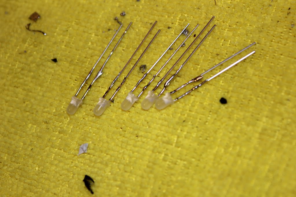
Now cut the leads shorter. You need them fairly short to ensure enough clearance. Also, be sure to cut them straight!
Tin your contacts on the board. This part is kind of silly when using the standard LED's shown. You actually can only use 2 of the 4 contacts on each LED mounting surface. If you connect to the wrong 2, or put too much solder on and it touches the connection beside it, the LED won't work.
Not that it matters, but this is because the old SMD's are actually two little lights in each, run in series diagonally through the board. So one contact goes in through the 1st SMD bulb and across to the other contact, then under the circuit board up through the other contact, and finally through the 2nd SMD bulb to the negative. Kind of like sewing on a button with 4 holes, if you know how that works....
Whoo hoo now you know why. Doesn't matter just hook them up like shown.
It's kind of dumb but not a big deal because you know about it! Imagine my surprise the first one I did
I've labled the contacts you need to use, they're diagonal each other:
You want to pre-tin these contacts for easy install. A little bit of flux on the contacts before tinning makes this job super easy and quick. You just want a little 'dot' or 'bubble' on the contact, it'll happen fast and smooth with flux and proper technique, you don't need to heat the circuit board up really at all just touch it and touch the solder to it and bam, tinned.
I took a video of my install, I'll edit it in soon. The acutal soldering process I can't help you with much but it's super easy if you pre-tinned everything. Just place, and give a quick touch with the soldering gun on one end, let it cool, then just a little touch on the other contact and you're good. Make sure you check your POSTIIVE and NEGATIVE during install, if you install it wrong it won't light up.
Enjoy!!
NOTE: If you have one or more that don't light up, don't panic. Take it back downstairs and have a close look. You've either
a) installed an LED backwards
b) Made contact on the wrong diagonal contact
c) allowed the contacts next to each other to touch each other
d) you have a faulty LED.
In any of these cases you should be able to just re-do the bad LED or bad connection, and re-test.
Note, under the LED's lens are two visible contacts. One is small, the other is large. The small contact INSIDE the lens is POSITIVE +
Make a note of this, you need to know it.
Shown is the positive lead:
Now, tin all 5 of your LED's for easy install:
Now cut the leads shorter. You need them fairly short to ensure enough clearance. Also, be sure to cut them straight!
Tin your contacts on the board. This part is kind of silly when using the standard LED's shown. You actually can only use 2 of the 4 contacts on each LED mounting surface. If you connect to the wrong 2, or put too much solder on and it touches the connection beside it, the LED won't work.
Not that it matters, but this is because the old SMD's are actually two little lights in each, run in series diagonally through the board. So one contact goes in through the 1st SMD bulb and across to the other contact, then under the circuit board up through the other contact, and finally through the 2nd SMD bulb to the negative. Kind of like sewing on a button with 4 holes, if you know how that works....
Whoo hoo now you know why. Doesn't matter just hook them up like shown.
It's kind of dumb but not a big deal because you know about it! Imagine my surprise the first one I did
I've labled the contacts you need to use, they're diagonal each other:
You want to pre-tin these contacts for easy install. A little bit of flux on the contacts before tinning makes this job super easy and quick. You just want a little 'dot' or 'bubble' on the contact, it'll happen fast and smooth with flux and proper technique, you don't need to heat the circuit board up really at all just touch it and touch the solder to it and bam, tinned.
I took a video of my install, I'll edit it in soon. The acutal soldering process I can't help you with much but it's super easy if you pre-tinned everything. Just place, and give a quick touch with the soldering gun on one end, let it cool, then just a little touch on the other contact and you're good. Make sure you check your POSTIIVE and NEGATIVE during install, if you install it wrong it won't light up.
Enjoy!!
NOTE: If you have one or more that don't light up, don't panic. Take it back downstairs and have a close look. You've either
a) installed an LED backwards
b) Made contact on the wrong diagonal contact
c) allowed the contacts next to each other to touch each other
d) you have a faulty LED.
In any of these cases you should be able to just re-do the bad LED or bad connection, and re-test.
Last edited by TunerMaxima3000; Feb 20, 2012 at 07:52 PM.
Member
Joined: May 2011
Posts: 72
From: Suffolk, Long Island
Great write-up/info Tuner..If I was more experianced in stuff like this I would love to do it but I would prob mess something up cause it seems like you need a lot of patience for this..although you do make it look relatively easy with all the pics.
Also an update on my cluster/sticky needles, it seems that they have improved...somehow ? I will post current video tomorrow and quote original video. I have not touched the cluster in between videos and you will see the difference. Although I have not tried putting stock bulbs back in to rule that out, have you ever seen something like this progressively improving?
Also an update on my cluster/sticky needles, it seems that they have improved...somehow
? I will post current video tomorrow and quote original video. I have not touched the cluster in between videos and you will see the difference. Although I have not tried putting stock bulbs back in to rule that out, have you ever seen something like this progressively improving?
You can use either 3mm standard LED's, or you can use a small SMD. I chose the standard LED, with a diffused lens.
Note, under the LED's lens are two visible contacts. One is small, the other is large. The small contact INSIDE the lens is POSITIVE +
Make a note of this, you need to know it.
Shown is the positive lead:
[IMG]More Quality Work[/IMG]
Now, tin all 5 of your LED's for easy install:
[IMG]More Quality Work[/IMG]
Now cut the leads shorter. You need them fairly short to ensure enough clearance. Also, be sure to cut them straight!
[IMG]More Quality Work[/IMG]
Tin your contacts on the board. This part is kind of silly when using the standard LED's shown. You actually can only use 2 of the 4 contacts on each LED mounting surface. If you connect to the wrong 2, or put too much solder on and it touches the connection beside it, the LED won't work.
Not that it matters, but this is because the old SMD's are actually two little lights in each, run in series diagonally through the board. So one contact goes in through the 1st SMD bulb and across to the other contact, then under the circuit board up through the other contact, and finally through the 2nd SMD bulb to the negative. Kind of like sewing on a button with 4 holes, if you know how that works....
Whoo hoo now you know why. Doesn't matter just hook them up like shown.
It's kind of dumb but not a big deal because you know about it! Imagine my surprise the first one I did
I've labled the contacts you need to use, they're diagonal each other:
[IMG]More Quality Work[/IMG]
You want to pre-tin these contacts for easy install. A little bit of flux on the contacts before tinning makes this job super easy and quick. You just want a little 'dot' or 'bubble' on the contact, it'll happen fast and smooth with flux and proper technique, you don't need to heat the circuit board up really at all just touch it and touch the solder to it and bam, tinned.
I took a video of my install, I'll edit it in soon. The acutal soldering process I can't help you with much but it's super easy if you pre-tinned everything. Just place, and give a quick touch with the soldering gun on one end, let it cool, then just a little touch on the other contact and you're good. Make sure you check your POSTIIVE and NEGATIVE during install, if you install it wrong it won't light up.
Enjoy!!
[IMG]More Quality Work[/IMG]
NOTE: If you have one or more that don't light up, don't panic. Take it back downstairs and have a close look. You've either
a) installed an LED backwards
b) Made contact on the wrong diagonal contact
c) allowed the contacts next to each other to touch each other
d) you have a faulty LED.
In any of these cases you should be able to just re-do the bad LED or bad connection, and re-test.
Damn you tuner always changing something up.so how much better are those 360 output leds and is there another source for them besides SBL? like bulk pricing reason i asked is one of my friends who's in a ford focus rally club wants me to do his 2 cars and a couple of the other members will prob want it done sense there using the stick on lights from the auto parts store he took pics of my crap and posted it on some focus forum to show the others.and today my 2 rolls of 5050 smd's came in pretty good quality for the cheap price and they are spaced really close together i should of got 1 Cool White and 1 RGB to tinker with.
I wouldn't even try buying the 360 degrees elsewhere, you're not going to save that much, and with the SBL you at least know what youre getting.
When I started I bought whatever cheap LED's and I spent a ton trying to find good ones. Once I did I found the price I had to pay was not too far from SBL, so now I just exclusively use them, unless I need something they don't have.
Also I never need to use as many with SBL's stuff, they're still better quality.
If you do want to get some 50 packs or 100 packs for cheap, Well-ton is the Ebay supplier I used to use for singular LED stuff like 3mm/5mm. Those are the ones I used in the Master switch above and throughout my car. The Gauges have 4 HPx3 blue alongside the barage of well-ton 3mm Blue diffused led's I put under the needles.
In short, yes, you can find them elsewhere, but at the end of the day it's probably a waste of your money and time if you demand high quality stuff. SBL is reasonable. Not like "Vleds" prices or anything (freaking ridiculous).
There are a lot of places you can use Well-ton's stuff though and save money. Window switches for example don't have to be super special LED's they just have to be the right size and colour, and of good enough quality to withstand soldering heat and acutally last.
Last edited by TunerMaxima3000; Feb 21, 2012 at 11:29 AM.

Gto the beginning of this thread where i did my manual unit and if you still need help just post it here and ill walk you thru cause i just did my 97 unit and its still dissambled so i can give you pics
ok I read the whole thread and CJ - Would LOVE pics of the stock OEM radio setup doing this as well (I saw the "radio prep" ones, did you actually do any changes with the radio? Do you think the 360* 5mm leds wiill work in that application as well?...but I didn't see where you specified you did this to your 97. I am assuming my 99 will be different from the 5th gen setup shown...
Last edited by Amerikaner83; Feb 21, 2012 at 01:04 PM.
ok I read the whole thread and CJ - Would LOVE pics of the stock OEM radio setup doing this as well (I saw the "radio prep" ones, did you actually do any changes with the radio? Do you think the 360* 5mm leds wiill work in that application as well?...but I didn't see where you specified you did this to your 97. I am assuming my 99 will be different from the 5th gen setup shown...
Alert! I am about to thread jack! so, if you are sensitive to that look away.
If anyone is looking for 360 LEDs I have a connection to the factory in China that makes them so I can get you some for half the price of superbright LEDs and I have a greater selection of sizes, power output, types (Lighting Grade) and colors. PM me for details.
If anyone is looking for 360 LEDs I have a connection to the factory in China that makes them so I can get you some for half the price of superbright LEDs and I have a greater selection of sizes, power output, types (Lighting Grade) and colors. PM me for details.
 If those 360* leds work for the climate on your 97 that'd be freaking sweet! And is the 03 factory radio the same or nearly identical to the 99?
http://www.led-switch.com/
They have 1.4mm, 1.6mm and 2mm LEDs which are good for the recirc / defroster lights on 5th gen HVAC.
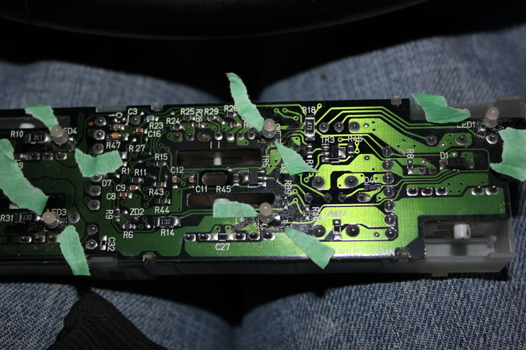
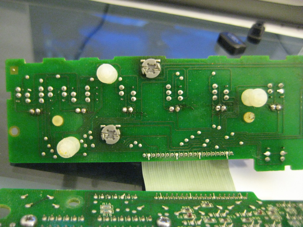
1997 Maxima A/C manual controls.
In this process i did not show pictures of the actual desolder/solder process as they are the exact same as other post on here and i forgot to take them pictures.
the following parts are needed from SuperBrightLed
4 - NEO3-W (White) get whatever color you are wanting
5 - 1/8 watt 470 ohm resistors from Radio Shack
10 -3mm Led's
Solder Wick or Sucker.
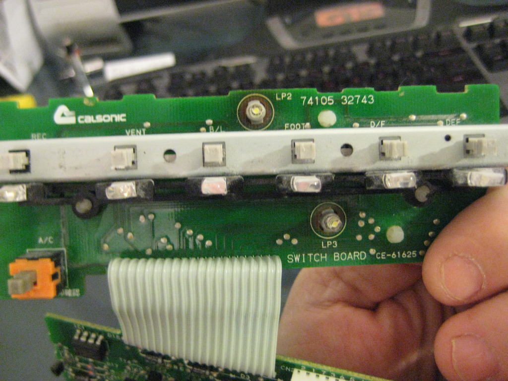
UNPLUG THIS WHITE CONNECTOR BEFORE PROCEEDING TO REMOVE BOARDS
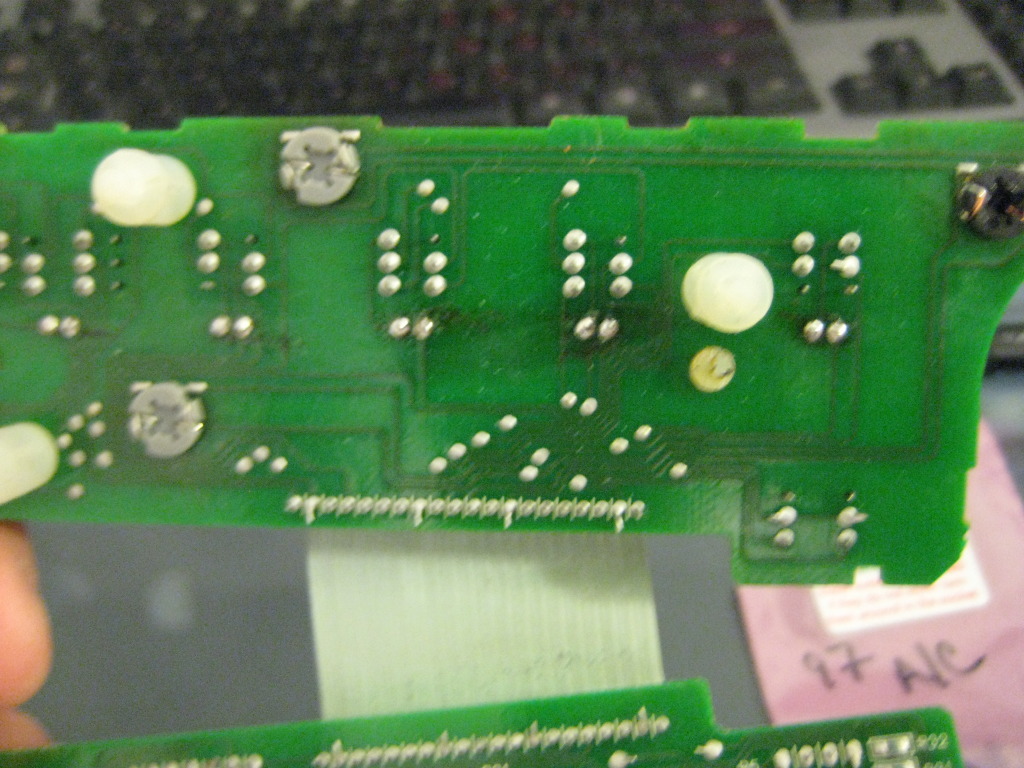
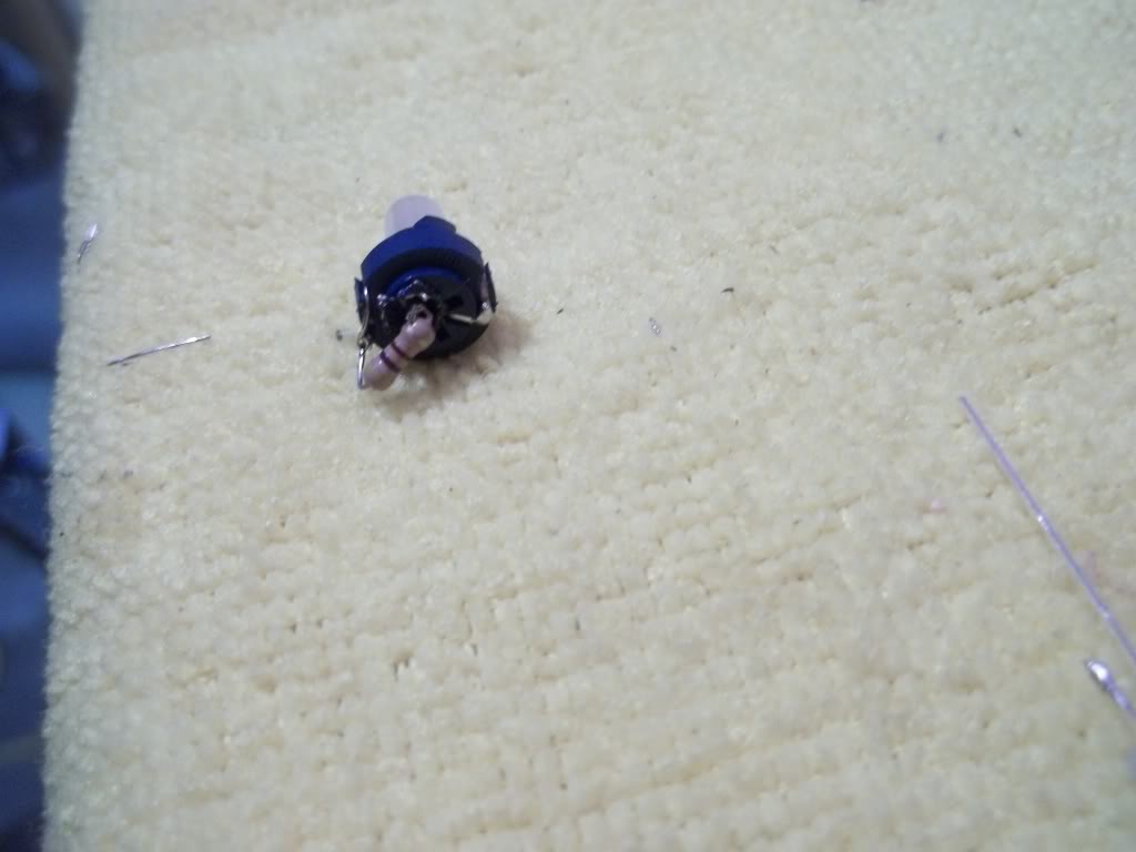
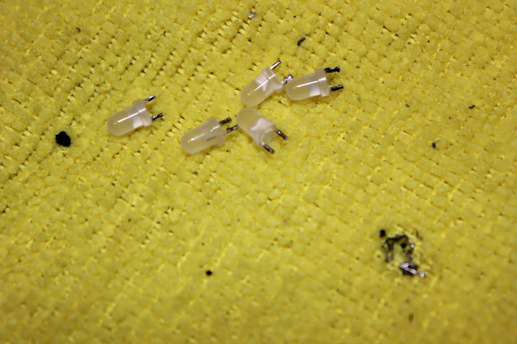
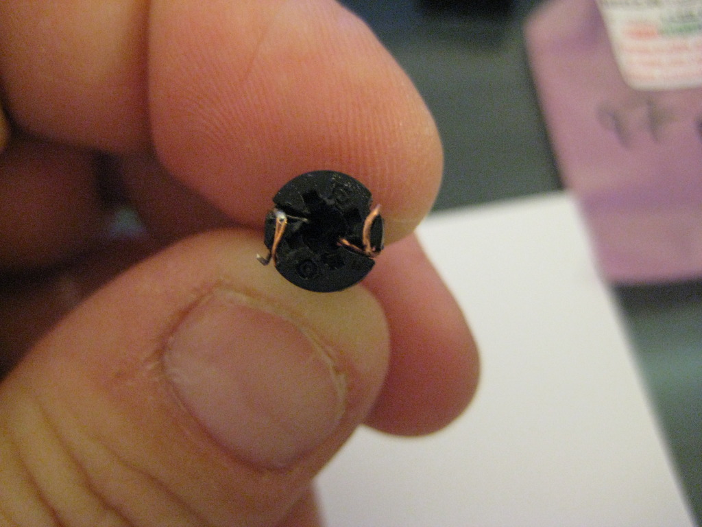
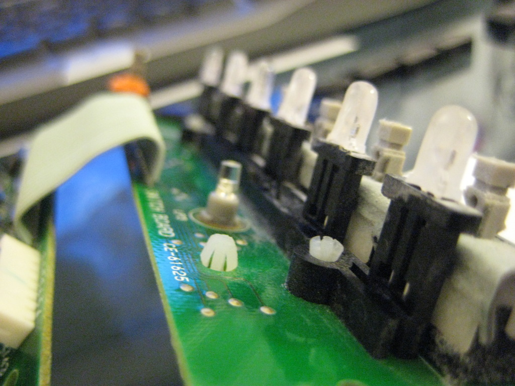
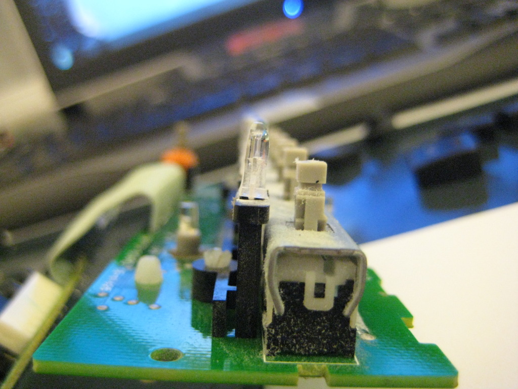
BELOW ARE EXAMPLES OF THE OLD AND NEW BULBS THE SBL ARE DIRECT REPLACEMENT EXCEPT FOR ONE WHERE YOU WILL HAVE TO TAKE APART THE SBL UNIT BY HEATING IT UP FOR A FEW SECONDS WITH A LIGHTER AND PULLING THE LED FROM THE GRAY BASE YOU WILL THEN INSERT THE SBL PIECE INTO THE OE BLACK BASE AND WRAP THE WIRE AROUND THE TABS.

HERE IS WHERE I SHOULD OF DONE MORE RESEARCH I SHOULD OF USED 3MM LED'S FOR THE BUTTONS I HAD USED 5MM AND WAS FORCED TO SAND THEM DOWN.DO NOT DO THIS JUST GET THE 3MM LED'S.WHEN REPLACING THE LED'S TAKE NOTE OF THE LOCATION OF THE +/- LOCATION ON THE 1997 UNIT THE GROUND OR SHORT LEAD IS ON YOUR RIGHT IF YOU ARE LOOKING AT THE BOARD FROM THE BACK AS SEEN IN THE ABOVE PICTURES.
ALWAYS TEST THE UNIT BEFOR YOU PUT IT COMPLETLY BACK TOGETHER MAKE SURE WHEN YOU DO TEST IT TO PLUG THE WHITE CONNECTOR INTO THE MAIN BOARD IT IT WONT TURN ON.
In this process i did not show pictures of the actual desolder/solder process as they are the exact same as other post on here and i forgot to take them pictures.
the following parts are needed from SuperBrightLed
4 - NEO3-W (White) get whatever color you are wanting
5 - 1/8 watt 470 ohm resistors from Radio Shack
10 -3mm Led's
Solder Wick or Sucker.
UNPLUG THIS WHITE CONNECTOR BEFORE PROCEEDING TO REMOVE BOARDS
BELOW ARE EXAMPLES OF THE OLD AND NEW BULBS THE SBL ARE DIRECT REPLACEMENT EXCEPT FOR ONE WHERE YOU WILL HAVE TO TAKE APART THE SBL UNIT BY HEATING IT UP FOR A FEW SECONDS WITH A LIGHTER AND PULLING THE LED FROM THE GRAY BASE YOU WILL THEN INSERT THE SBL PIECE INTO THE OE BLACK BASE AND WRAP THE WIRE AROUND THE TABS.
HERE IS WHERE I SHOULD OF DONE MORE RESEARCH I SHOULD OF USED 3MM LED'S FOR THE BUTTONS I HAD USED 5MM AND WAS FORCED TO SAND THEM DOWN.DO NOT DO THIS JUST GET THE 3MM LED'S.WHEN REPLACING THE LED'S TAKE NOTE OF THE LOCATION OF THE +/- LOCATION ON THE 1997 UNIT THE GROUND OR SHORT LEAD IS ON YOUR RIGHT IF YOU ARE LOOKING AT THE BOARD FROM THE BACK AS SEEN IN THE ABOVE PICTURES.
ALWAYS TEST THE UNIT BEFOR YOU PUT IT COMPLETLY BACK TOGETHER MAKE SURE WHEN YOU DO TEST IT TO PLUG THE WHITE CONNECTOR INTO THE MAIN BOARD IT IT WONT TURN ON.
Thanks! Couple questions -
*Where did you use the resistors?
*The 10 3mm LEDs are for the indicators under the buttons, yes? I am thinking of using blue on the indicator buttons and white on the background.
*The NEO3 are the background ones, yes?
*Where did you use the resistors?
*The 10 3mm LEDs are for the indicators under the buttons, yes? I am thinking of using blue on the indicator buttons and white on the background.
*The NEO3 are the background ones, yes?
the resistors are just incase you break the one off the NEO when replacing it $1.89 is worth the insurance plus you will need them for other things like switches and such. the 3mm are for all the button leds as well as the slider.correct the NEO3 are the background ones.remember to always get a few extra for the just in case and always test before and after you install them to advoid hastle use a 9v battery and one of the resistors to test and the + is the longer lead of the led.
the resistors are just incase you break the one off the NEO when replacing it $1.89 is worth the insurance plus you will need them for other things like switches and such. the 3mm are for all the button leds as well as the slider.correct the NEO3 are the background ones.remember to always get a few extra for the just in case and always test before and after you install them to advoid hastle use a 9v battery and one of the resistors to test and the + is the longer lead of the led.
How is the hotspotting with the neo LEDs?
I'm doing the window switches here @ work now... :-)
Last edited by Amerikaner83; Feb 22, 2012 at 11:41 AM.
I havnt tried it yet but if you follow Tuners post above you can simply swap out the OE bulbs from the holders for the 360 leds from sbl and just add the resistor.
Can't go off that bro, it changes from different LED styles and different suppliers. you have to go off the contacts INSIDE the LED lens. The smaller one is Positive, always.
That and 9/10 you end up cutting or modding the long contacts anyways.
And if there's any doubt always test first to identify, if installing in a spot where it's important. The twist and lock is not important, cause if it's wrong, you just have to turn the socket 180*, no re-soldering or anything.
This is the route I'd be going with any of the background/main illumination LED's