
View Poll Results: 5th Gen LED mod thread, Yepe or Nepe?
I'd read it, maybe even subscribe to it, but I'd never actually have the balls to do it on my car


15.22%


I've already done it, but would like to contribute my experience and technique to this thread


15.22%
Voters: 46. You may not vote on this poll
How to LED your 5th gen _~ Feeler thread .w. POLL


no problem just put the holder in the hole first then slip the led in from the other side.or you can sand the lip off the bottom of the led but be carefull anytime you heat up a led if the contacks get hot enuff to loosen inside its going to give you issues.personally i would just verry carefully enlarge the hole in the board itself this is something you may not want to do if you dont have a spare unit around to test on.
Yeah I love my new T2i, haven't even scratched the surface of it's capabilities though, I've been using it almost like a point and shoot lately. Springtime I'll mess around probably.
And here's a 5mm:
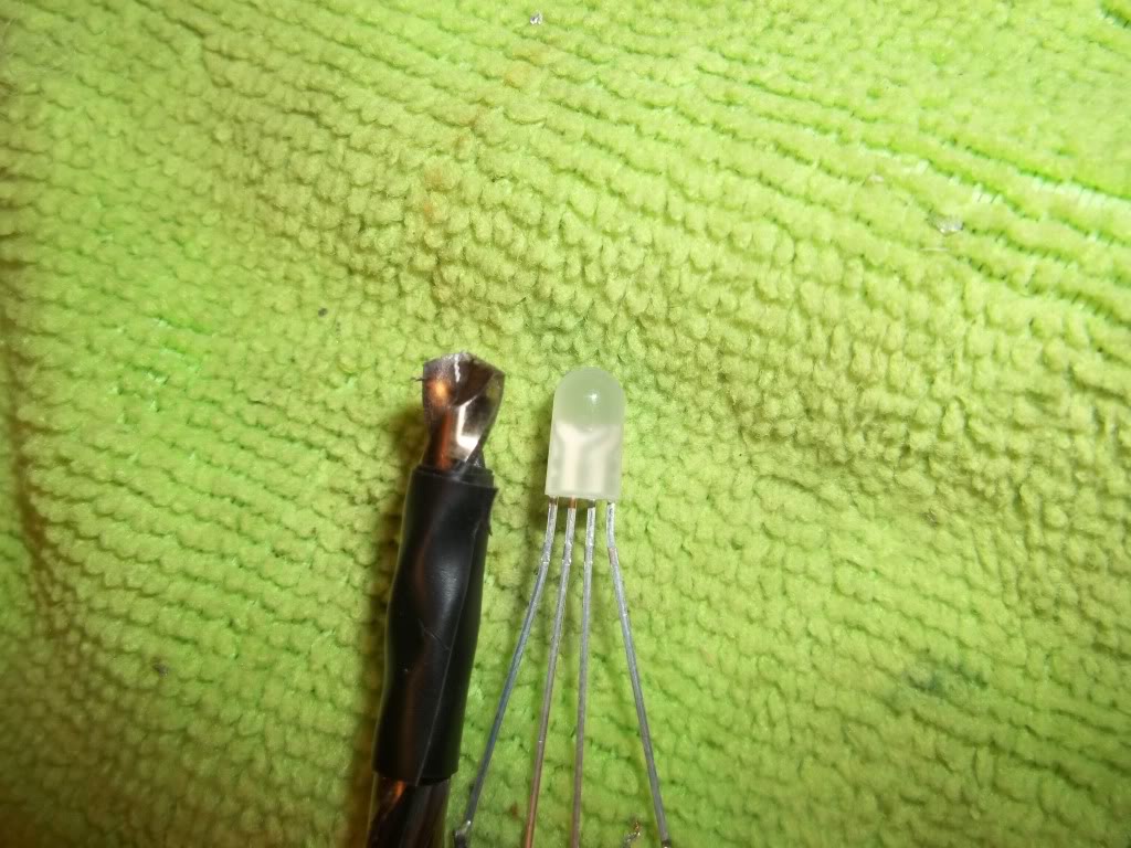
And a 5050 RGB common Anode:

And here's a 5mm:
And a 5050 RGB common Anode:
I do have one tip for everyone deciding to do LED modification and that is reverse polarity protection. I don't see anyone using a 1N4148 diode or a 1N4938 diode which is a definite must have if you want maximum half life out of your LEDs. Otherwise everytime you turn on your car and the LEDs are on you risk reverse polarity overvoltage damage. Which might not kill your LEDs but it will cause them to dim quick than they would overwise. If you are unlucky that can definity kill them however.

The ones I show are Common Anode. The Positive connection is ALL 3 points on the one side of the SMD. Then the ground side is separated into Green, Red and Blue.
You can get this same thing in common cathode and run power to the RGB side and ground on the other. Makes more sense to have common Anode to me for any application I can think of.
I do have one tip for everyone deciding to do LED modification and that is reverse polarity protection. I don't see anyone using a 1N4148 diode or a 1N4938 diode which is a definite must have if you want maximum half life out of your LEDs. Otherwise everytime you turn on your car and the LEDs are on you risk reverse polarity overvoltage damage. Which might not kill your LEDs but it will cause them to dim quick than they would overwise. If you are unlucky that can definity kill them however.
You can order Common Anode or Common Cathode.
The ones I show are Common Anode. The Positive connection is ALL 3 points on the one side of the SMD. Then the ground side is separated into Green, Red and Blue.
You can get this same thing in common cathode and run power to the RGB side and ground on the other. Makes more sense to have common Anode to me for any application I can think of.
Can you provide some more info/insight on this? Not something I'm even aware of TBH. I figure they're diodes so power can't flow backwards by that simple nature. Clearly I'm misled!
Last edited by Shinjiduo; Feb 23, 2012 at 01:41 PM.

Perhaps...I"m planning on doing my scheme like this: White climate control backlight, and blue indicators. I've got some 5mm 360* on order, I'll modify them into the stock housing and see how that turns out.
LEDs are diodes but like all diodes they have what is known as a breakdown voltage. When this number is hit (usually 2V, 5V or 10V) the diode loses its ability to stop current flow and it passes current unrestricted since LEDs do not have their own resistance. This does not cause the LED to light up but it damages the LED all the same. You might not notice it right away but if you compare the light degradation of a LED that is reverse polarity protected in a car and one that is not after a year you will notice the unprotected one is dimmer. In some cases a large enough spike can even go through your system to seriously damage LEDs instantly if you are unlucky. All the switching or rectifying diode does is make sure the electricity is always going through the LED properly by switching polarity if it reaches its breakdown voltage (which is lower than any LEDs max reverse voltage) or shuts the current down when it encounters a reverse current. This ensures max brightness of your LED for as long as it can last. You will never see a quality LED replacement bulb without a switching diode, rectifier diode or dual postive current Integrated circuit (too complex so I don't use IC's). I just notice no one is using them here and am giving a piece of advice that is all.
And where would you recommend I get them from, doesn't matter?
Thanks again, can these be applied to the ground side of the circuit? ie. I have already wired my 5050 RGB SMD's into all my window switches, can I just install one on each of the 3 main ground runs at each window switch OUT and be ok?
Great info thanks for taking the time to break this down for me man! I will have to get my paws on some of these, different rating for 5050 smds than for the standard 3 and 5mm ones?
And where would you recommend I get them from, doesn't matter?
Thanks again, can these be applied to the ground side of the circuit? ie. I have already wired my 5050 RGB SMD's into all my window switches, can I just install one on each of the 3 main ground runs at each window switch OUT and be ok?
And where would you recommend I get them from, doesn't matter?
Thanks again, can these be applied to the ground side of the circuit? ie. I have already wired my 5050 RGB SMD's into all my window switches, can I just install one on each of the 3 main ground runs at each window switch OUT and be ok?
A 1N4148 will be fine for 3 chip 5050 SMDs. I always attach to the ground side when I do mine so you should be fine. Just make sure if you attach to the ground side that the black strip is on the side opposite of the LED. If you attach it wrong the LED will only light up when the lights are switched off. Also, the master switch is already equipped with protection IC so you do not have to worry about that as for the rest of the window switches They are probably attached to some relay or something of the sort for protection however, if you just want to be sure like myself as said before you will be fine with a 1N4148 fast switching diode which you can get from ebay. I think the best value you can get is from a ebay vendor named thaishine.
I did'nt do much testing to figure this out cause I didn't care it was faster to just wire it the way I knoew would work.
So will 1 of these diodes on each ground line work? that would mean 5 3 chip SMD's all spliced together into 3 ground lines. Then ONE diode per ground line.
i think if you did 1 5a 1000v diode on the main ground trace you would be ok.thats all we used to use when we rebuilt alternator rectifiers to reduse the back current draw when it wasnt charging
If i'm taking it in correctly though, the small amperage rating of these little led/smd's requires a FAST switching and relatively low rated diode. Something like what you're talking about would probably allow enough current through, no?
i dont know a lot about this stuff though, in either case, I've got those bad boys coming so if I need something else or need to install more than one in line, or whatever, LMK Shin. Luckily the Window switches have been the only component SMD install so far, the rest has been Ribbon strips which have worked out way better than expected.
i dont know a lot about this stuff though, in either case, I've got those bad boys coming so if I need something else or need to install more than one in line, or whatever, LMK Shin. Luckily the Window switches have been the only component SMD install so far, the rest has been Ribbon strips which have worked out way better than expected.

Worked on a few things... Replaced the LED in the clock for my security:

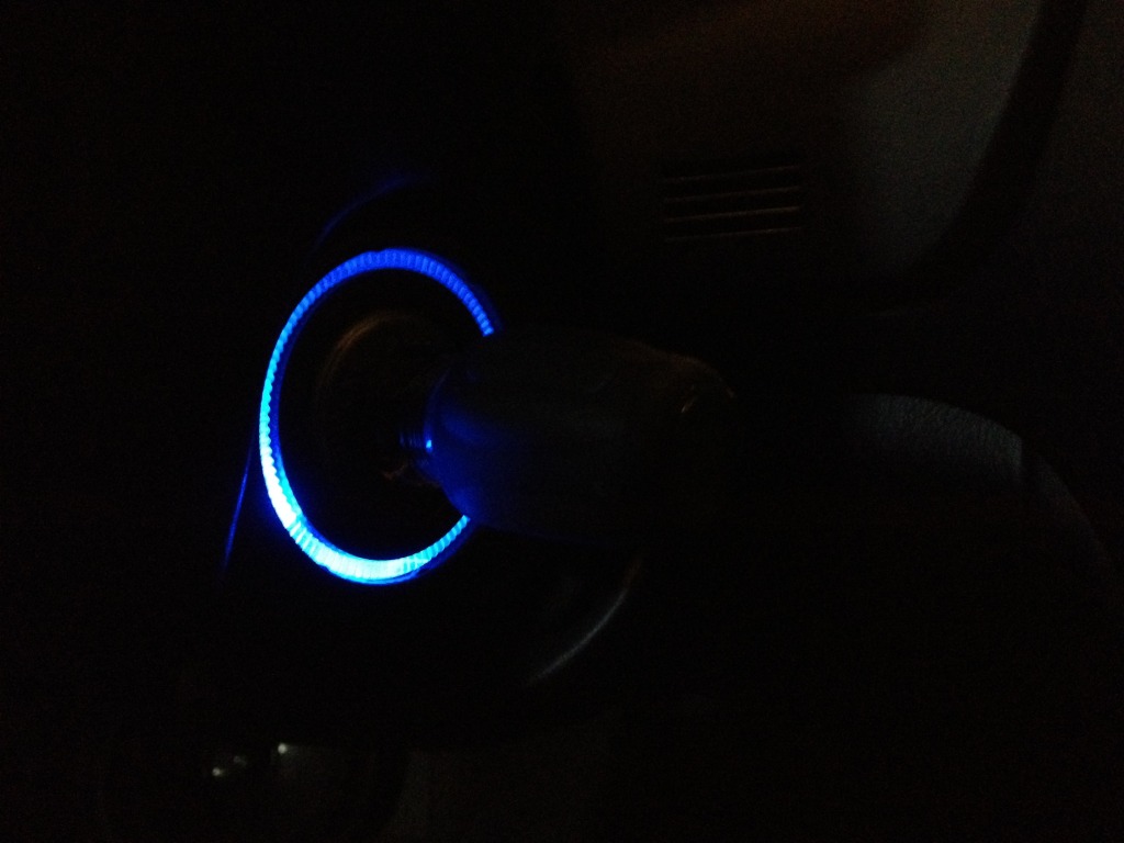
Replaced the light in the key ring with a blue LED (looks more uniform in person):

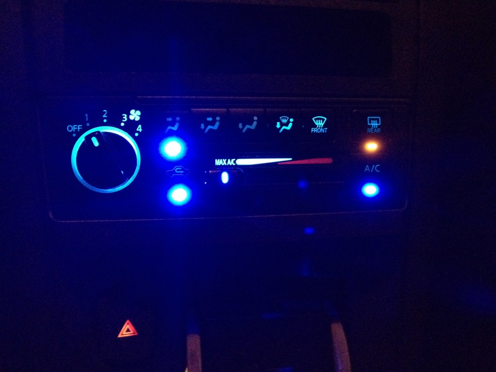
Replaced all the lights in the climate control and hazard button. (bulbs also look more uniform in person) but it looks like some of the buttons are a bit dim... Will change the 3 drop in's with 360� LED's in the near future.
Replaced the light in the key ring with a blue LED (looks more uniform in person):
Replaced all the lights in the climate control and hazard button. (bulbs also look more uniform in person) but it looks like some of the buttons are a bit dim... Will change the 3 drop in's with 360� LED's in the near future.


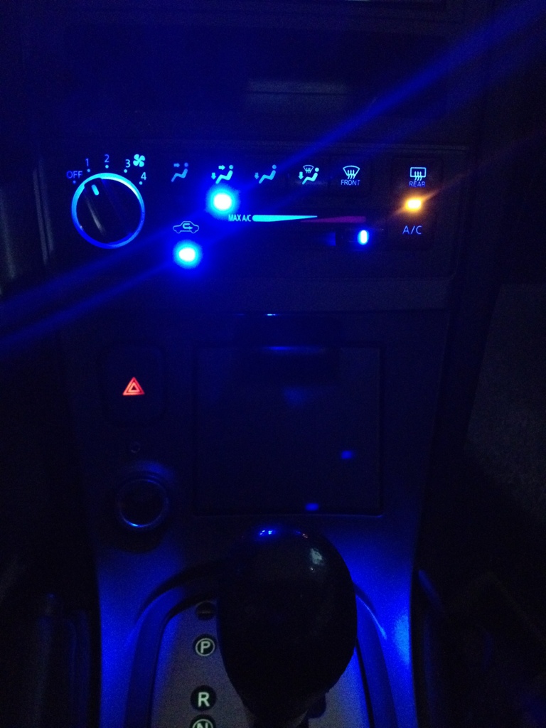
360 LEDs are insane! Did it to my 99's manual CC finally, WOW. And something I found to dim the indicator LEDs since they're hella bright...sand them a bit, and put a thin layer of white-out on it. It'll still show through, but be a nice softer shade of blue than the "give you a migraine second coming of Jesus" blue otherwise.
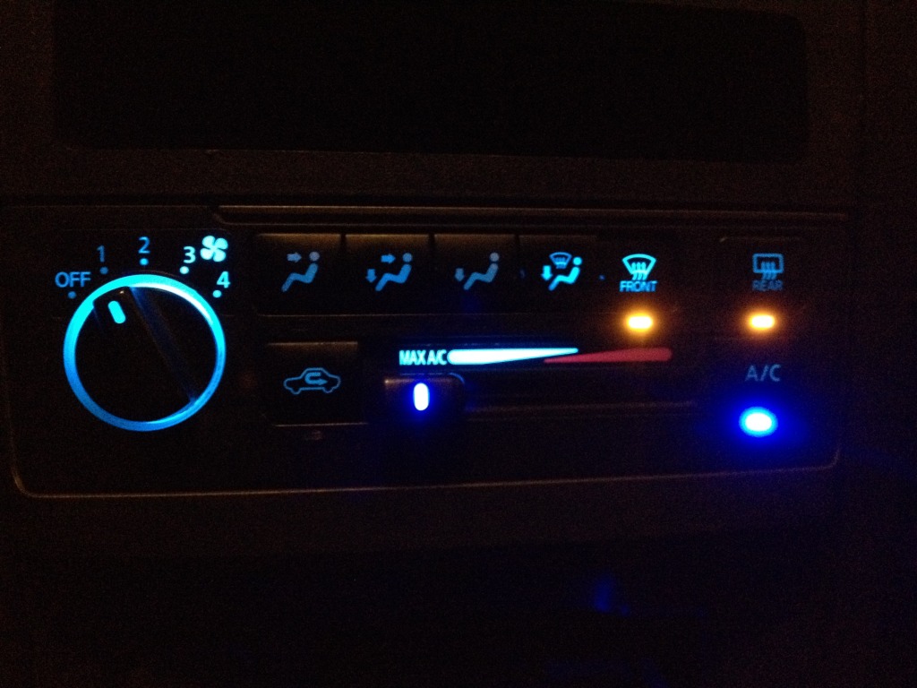
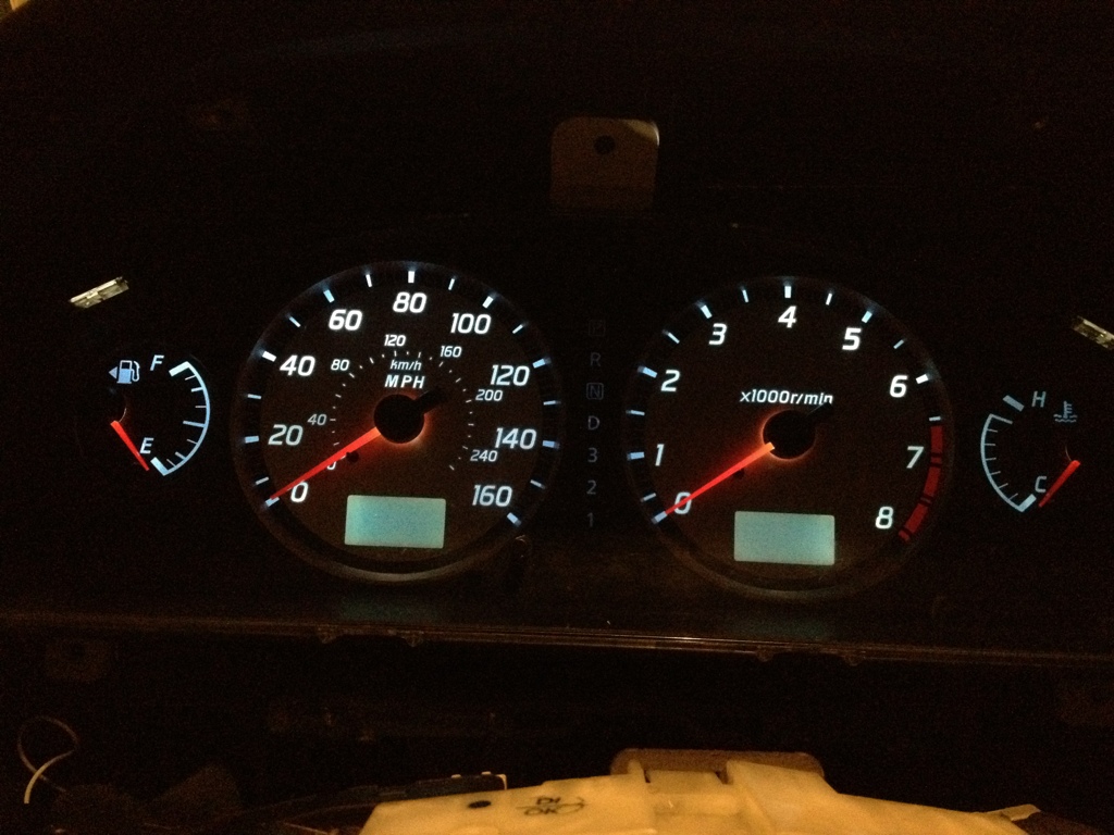
First LED setup with bright azz indicators:
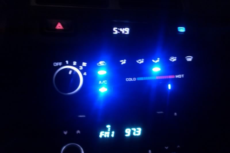
Will post the "after" when I get home this evening in the dark garage. Did the change during lunch today, super easy...and the indicators are still absolutely visible during the day, but like I said, not as blinding during the night.
First LED setup with bright azz indicators:
Will post the "after" when I get home this evening in the dark garage. Did the change during lunch today, super easy...and the indicators are still absolutely visible during the day, but like I said, not as blinding during the night.
Last edited by Amerikaner83; Mar 2, 2012 at 02:37 PM.
360 LEDs are insane! Did it to my 99's manual CC finally, WOW. And something I found to dim the indicator LEDs since they're hella bright...sand them a bit, and put a thin layer of white-out on it. It'll still show through, but be a nice softer shade of blue than the "give you a migraine second coming of Jesus" blue otherwise.
First LED setup with bright azz indicators:

Will post the "after" when I get home this evening in the dark garage. Did the change during lunch today, super easy...and the indicators are still absolutely visible during the day, but like I said, not as blinding during the night.
First LED setup with bright azz indicators:
Will post the "after" when I get home this evening in the dark garage. Did the change during lunch today, super easy...and the indicators are still absolutely visible during the day, but like I said, not as blinding during the night.
Yeah Shinjiduo really come through on that one, it's a bloody revolution.
And the blinding indicator lights are the reason I've never modded one since my first one. It's really just not necessary. I actually prefer the OEM red/orange indicators the Maxima has stock anyways, just the perfect brightness and colour. Offsets all the blue.
And the blinding indicator lights are the reason I've never modded one since my first one. It's really just not necessary. I actually prefer the OEM red/orange indicators the Maxima has stock anyways, just the perfect brightness and colour. Offsets all the blue.
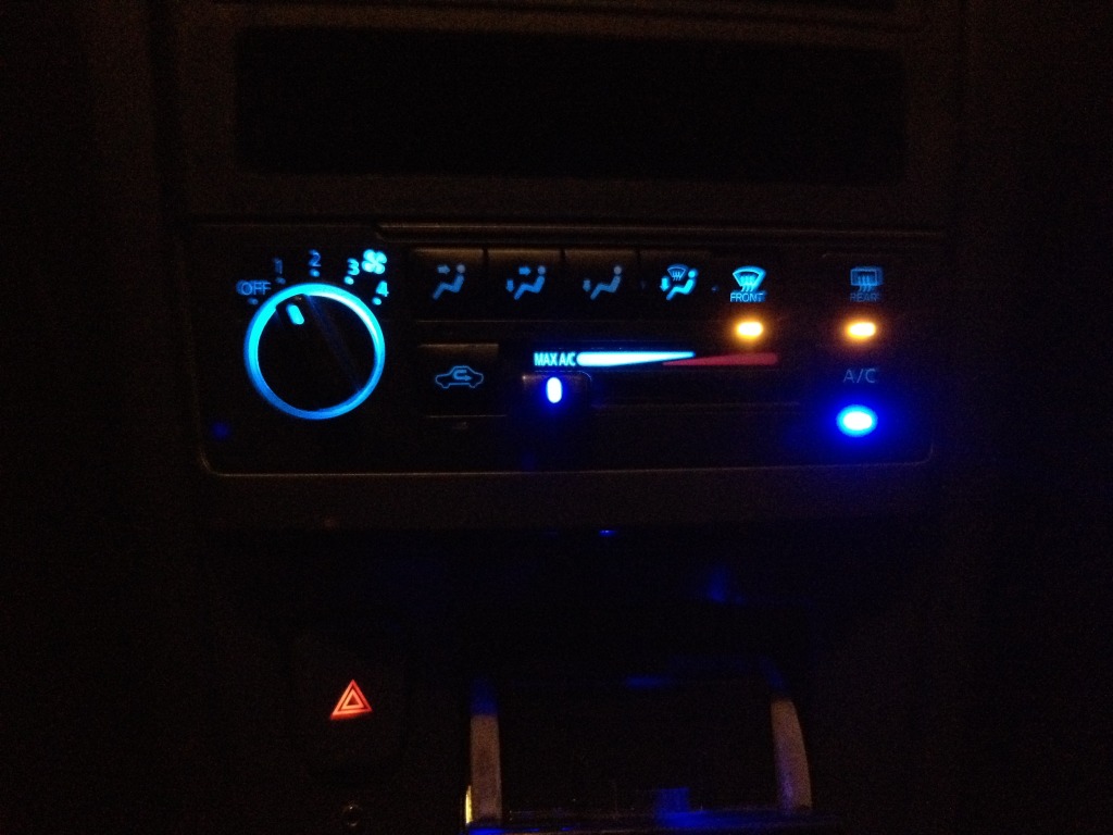
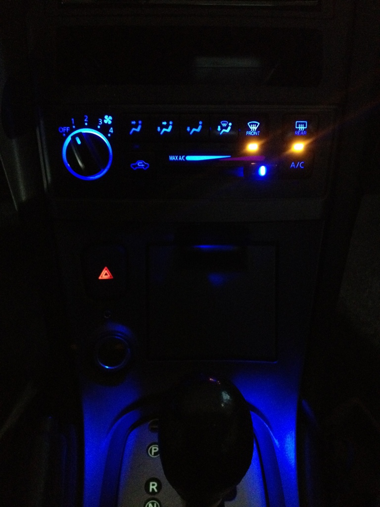
But like I said earlier, the blinding is greatly reduced by sanding and white-out applied to the LED itself.
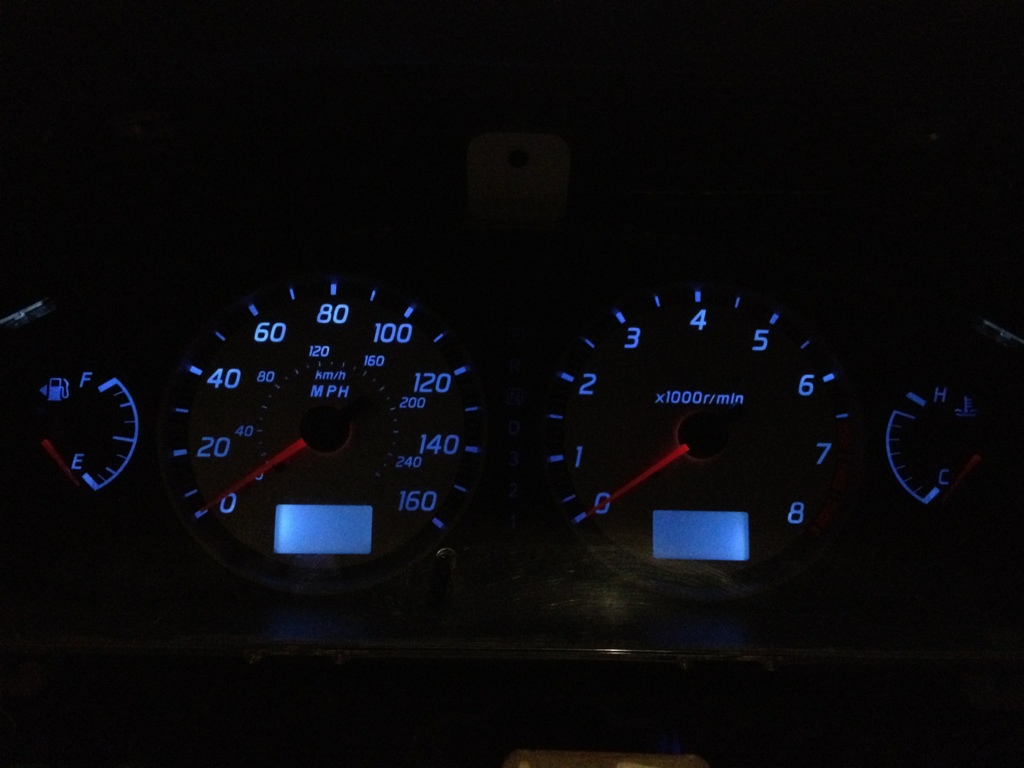
Here's the "after"... LEDs sanded and thin application of wite-out applied to them...
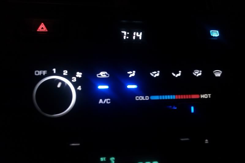
Not sure if the difference in the indicator lights really shows in the pic...but in person its perfect. Color still there, but not blindingly bright. Love it
Not sure if the difference in the indicator lights really shows in the pic...but in person its perfect. Color still there, but not blindingly bright. Love it
Nice dude! White out was a good idea, are you worried about it melting though? I would think it'll be ok but I always worry about those things. Hot glue especially, with it's relatively low melting point.
i've been using plastic epoxy for a lot of stuff lately to be on the safe side. great technique man thanks for sharing!!
i've been using plastic epoxy for a lot of stuff lately to be on the safe side. great technique man thanks for sharing!!
All white out is just paint. I'm not at all worried about it melting or anything, no. I actually used a paint pen we have @ work, but white out is more available commercially.
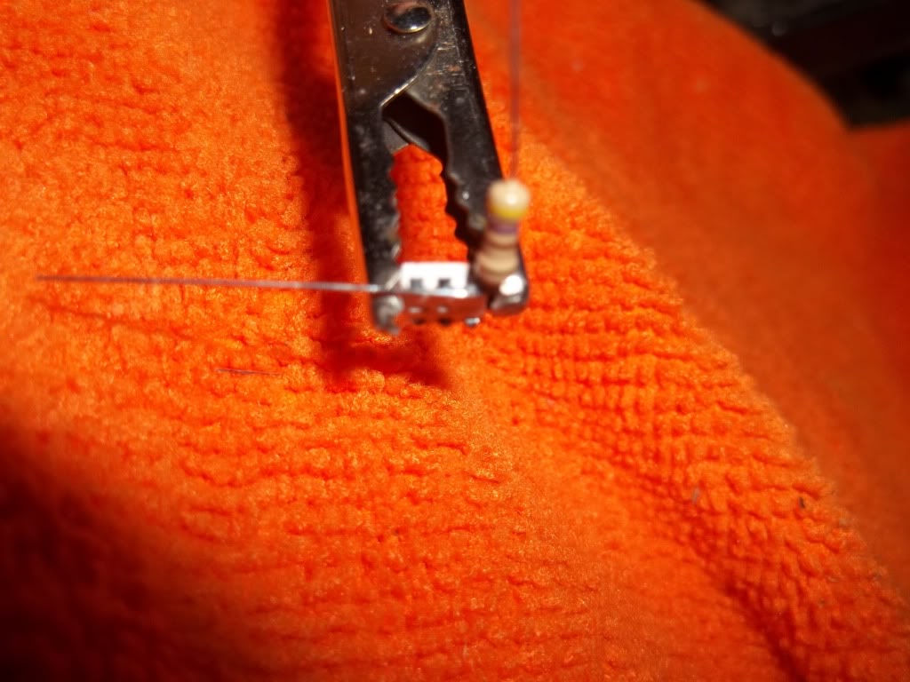
Honestly, I wasn't sure if it would turn out as well as it did. I just took a spare LED and sanded it until it was cloudy all around. Powered it with a 9V and resistor, was still too bright...so I was like "sure what the hell". Let it dry and it was perfect!
Honestly, I wasn't sure if it would turn out as well as it did. I just took a spare LED and sanded it until it was cloudy all around. Powered it with a 9V and resistor, was still too bright...so I was like "sure what the hell". Let it dry and it was perfect!