

MAF placement, TB to IM distance, Cam Pulse? Other Effects?

Thread Starter

Joined: Jul 2006
Posts: 1,172
From: St. Louis, MO
MAF placement, TB to IM distance, Cam Pulse? Other Effects?
Alright, I'm staying N/A for now, and I'm getting a curious/picky about little details. I've been searching and can't find definitive answers. I don't really need to make a larger MAF housing, but I would like to ensure it's getting the most accurate readings possible. I've also been playing with intake setups and thinking about a PF TB.
I've heard that having the MAF too close to the IM will increase the effects of "cam pulse" and throw off MAF readings. Seems logical to me... But at the same time, I've heard that MAF readings can be scewed due to turbulence if the MAF is placed too close to the filter. Is there truth to either of these? Which would have a greater effect? I'm thinking the MAF should be closest to the filter, to avoid cam pulse, and then a POP charger could be used to reduce turbulence. Maybe?
Also, When considering the PF TB, I thought of making my own adapter to the 00VI, but it would be an elbow, not a spacer. Spacers are typically pretty thin, maybe an inch or two, but if I fabbed an elbow that was several inches longer than a spacer, what would be the effect? The only reason for the elbow would be to point the TB in a different direction. I'm just wondering if creating such a greater distance between the TB and IM would adversely affect performance. Anyone know?

Thread Starter
Joined: Jul 2006
Posts: 1,172
From: St. Louis, MO
http://forums.focaljet.com/svt-headq...-location.html
I know it's a focus forum...but that's where I heard "cam pulse."
He gives no explanation, but I suppose I took it to mean some sort of resonance or pressure waves generated by the cams opening and closing
Here's a better explanation of what I was thinking: If the MAF close to the engine, it may see short spurts of air, as each cylinder draws in air. If you place the MAF further away, it would not see short little spurts, but one continuous flow. It probably doesn't affect anything, and my thinking is just probably incorrect.
Last edited by mowgli29; May 6, 2008 at 09:15 AM.
Either way you look at it, cam pulse is a misnomer. Maybe he means the reversion that occurs at low RPM when the intake charge is pushed out of the cylinder before the valve has a chance to close. This is only the case at low RPM. From peak torque (which is roughly equivalent to peak VE) on up, this is a non-issue.
I'd venture to say though, that a filter placed on the end of a MAF with no velocity stack in between is worse for turbulance than "intake reversion".
I'd venture to say though, that a filter placed on the end of a MAF with no velocity stack in between is worse for turbulance than "intake reversion".
Thread Starter
Joined: Jul 2006
Posts: 1,172
From: St. Louis, MO
I'm going to have to read up on "reversion."
So would a velocity stack take care of the turbulence? Would the difference from that be negligable as well?
Also, any idea about the PF TB adapter? Would it hurt performance to have the TB so far from the IM. Any idea what the specific effect would be?
So would a velocity stack take care of the turbulence? Would the difference from that be negligable as well?
Also, any idea about the PF TB adapter? Would it hurt performance to have the TB so far from the IM. Any idea what the specific effect would be?
Last edited by mowgli29; May 6, 2008 at 09:25 AM.
I'm going to have to read up on "reversion."
So would a velocity stack take care of the turbulence? Would the difference from that be negligable as well?
Also, any idea about the PF TB adapter? Would it hurt performance to have the TB so far from the IM. Any idea what the specific effect would be?
So would a velocity stack take care of the turbulence? Would the difference from that be negligable as well?
Also, any idea about the PF TB adapter? Would it hurt performance to have the TB so far from the IM. Any idea what the specific effect would be?
Last edited by DandyMax; May 7, 2008 at 09:30 PM.

When I was NA the best intake setup I had was the shortest possible. It was...
TB> Coupler> 3" MAF (or your MAF since you say you want to keep the stocker)> Cone
From TB mouth to tip of filter the whole thing was no longer than 11".
I never had any problems with faulty readings on the MAF. So that should answer both of your concerns; too close to TB (mine was right infront of it, coupler connecting them), and Filter right at the front (my air filter was clamped to the MAF itself, lol)

ok by cam pulse.. i think you mean valve pulse.. IM manifold design is based around a resonance (impulse) that is generated from the opening and closing of the valves.. the easiest way to understand it is a resistance in the flow of air in the intake runners... this resonance bounces off of the walls of your intake runners.. perfect example is the throaty sound you get when you do WOT in a 4th gen compared to the less throaty sound you with the dek.. because on the 4th gen you IM comes up a short distance and instantly does a 90.. as with the VI (dek IM) its a long sweeping runner.. but all in all that throaty growl you hear out of the 4th gens is resonance.. as for it making an interference with your MAF.. i dont see that happening.. but then again how close are you going to get your MAF to the TB also? as for turbulence in the MAF thats what the screen is for on the stock MAF.. that directs the air for a laminar flow throughout the MAF housing for a more accurate reading.. oh yeah.. and unless youre going to go forced induction.. i wouldnt worry about getting a larger TB just get a larger MAF housing.. thats gonna show more gains..
Thread Starter
Joined: Jul 2006
Posts: 1,172
From: St. Louis, MO
ok by cam pulse.. i think you mean valve pulse.. IM manifold design is based around a resonance (impulse) that is generated from the opening and closing of the valves.. the easiest way to understand it is a resistance in the flow of air in the intake runners... this resonance bounces off of the walls of your intake runners.. perfect example is the throaty sound you get when you do WOT in a 4th gen compared to the less throaty sound you with the dek.. because on the 4th gen you IM comes up a short distance and instantly does a 90.. as with the VI (dek IM) its a long sweeping runner.. but all in all that throaty growl you hear out of the 4th gens is resonance.. as for it making an interference with your MAF.. i dont see that happening.. but then again how close are you going to get your MAF to the TB also? as for turbulence in the MAF thats what the screen is for on the stock MAF.. that directs the air for a laminar flow throughout the MAF housing for a more accurate reading.. oh yeah.. and unless youre going to go forced induction.. i wouldnt worry about getting a larger TB just get a larger MAF housing.. thats gonna show more gains..
i have a 3" ID MAF housing on mine right now.. had to hack up the stocker.. which was pretty scary.. but it went very smoothly considering.. anyways i have had no troubles with mine.. car idles better than it did before.. but then again i have a VI soo.. i have noticed a considerably diff from 1.5K-3K.. car pulls hard.. and then i noticed with my a/c on car still has a nice pull througout, which i havent had since i had my stock crank pulley on.. and this is all w/o tuning on the dyno.. of course i have a safc2 to convert the signal.. but i can tell it would still need a tune.. imo i would def get this mod instead of/before getting a larger TB..
about your volume question.. i wouldnt consider the placement of your MAF a change in volume for your IM.. simply because most all of the impulses that are created wont travel past your butterfly valve for the TB.. they all travel lengthwise down the IM runners and then are all lost in the main bulk of the plenum (due to the sudden increase in pressure and decrease in velocity).. so seeing as these impulse waves are the main tuning parameters for your IM then i dont think that the placement of you MAF (change of ~6 inch or so) would make any noticeable diff.. if that makes sense
about your volume question.. i wouldnt consider the placement of your MAF a change in volume for your IM.. simply because most all of the impulses that are created wont travel past your butterfly valve for the TB.. they all travel lengthwise down the IM runners and then are all lost in the main bulk of the plenum (due to the sudden increase in pressure and decrease in velocity).. so seeing as these impulse waves are the main tuning parameters for your IM then i dont think that the placement of you MAF (change of ~6 inch or so) would make any noticeable diff.. if that makes sense
Thread Starter
Joined: Jul 2006
Posts: 1,172
From: St. Louis, MO
^^ starting to sound very tempting...My friend totaled his car so I have a MAF I can hack up...I'm tempted to run to lowes and get some pvc, but I recall SR20DEN having someone tell him pvc was a no no. What did you use to make the 3" MAF?
I have a VI as well but I'm worried about about not having enough correction points on my V-AFC2. I need all the correction points I can get from about 2500^ What kind of corrections did you end up making? Any? Maybe We should take the 3" MAF talk to PM's, it's sorta OT right?
Also, I wasn't really talking about the TB to IM distance in relation to the whole valve pulse thing. Just wondering if it's a bad idea in general...I was kinda wondering about the two as separate issues.
I've decided my original questions are probably just non-issues. Velocity stack will be good for peace of mind and maybe I'll be enlarging the MAF housing... IF/when I get a pathy TB, I'll just use spacer type adapter and call it a day. I'd rather spend that money on upgrading to an EU or some fender braces or something though...
I'll be playing with MAF housings and different intake setups over the summer, mostly just to see differences in throttle response/low end driveability. I'll post what I come up with...
I have a VI as well
but I'm worried about about not having enough correction points on my V-AFC2. I need all the correction points I can get from about 2500^ What kind of corrections did you end up making? Any? Maybe We should take the 3" MAF talk to PM's, it's sorta OT right?Also, I wasn't really talking about the TB to IM distance in relation to the whole valve pulse thing. Just wondering if it's a bad idea in general...I was kinda wondering about the two as separate issues.
I've decided my original questions are probably just non-issues. Velocity stack will be good for peace of mind and maybe I'll be enlarging the MAF housing... IF/when I get a pathy TB, I'll just use spacer type adapter and call it a day. I'd rather spend that money on upgrading to an EU or some fender braces or something though...
I'll be playing with MAF housings and different intake setups over the summer, mostly just to see differences in throttle response/low end driveability. I'll post what I come up with...
Originally Posted by mowgli29
pvc was a no no.

Ok, here is a short step by step. Hope this helps.
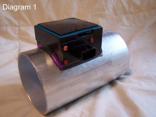
1. Use a razor or exacto knife(#11 blade works well) to remove the seal around the edge of the cap. The seal is highlighted in blue on diagram 1.
2. Use the combination of a small flat head screw driver and your exacto knife to pry open the cap. You can see from the picture, I accidentally broke the wall of mine, this is no big deal as once I get it running, I am going to seal it back off with liquid gasket.
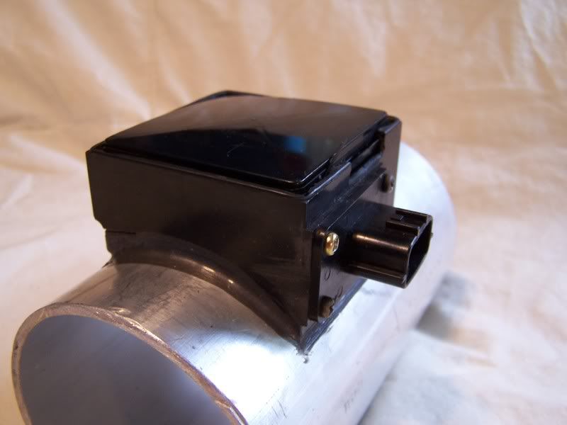
3. Remove the four outer screws on the plug itself. Be careful not to strip them, they arent easy. These are highlighted in red on diagram 1. DO NOT PULL ON THE PLUG!
4. Next, there will be a brass protector just under the plastic cap you just removed. It comes straight out, but may need some prying.
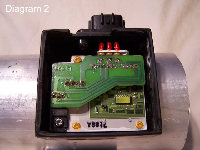
5. Here comes the harder part. You need to disconnect the main harness from the inside circuitry. The three contacts are highlighted in red in diagram 2. You have two options here:
a. The easy/fast yet risky way: Use a small flathead screw driver to break the 3 contacts to the plug from the leads off of the main circuit board. Just pry. They will come off. But too much stress and they will break. If they do, you will need to solder a new connection in.
b. The proper way: Simply use a soldering iron to heat up the solder joint, while using a small flathead to pry at the same time. No breaking, no risk.
6. Remove the three screws in the main circuit board. These are highlighted in orange in diagram 2.
7. Use a medium flathead to CAREFULLY! pry the main circuit board out of the housing. There is a rubber seal, and what I believe is locktite holding it in. Stick the screwdriver through the hole where the sensor plug came out of.
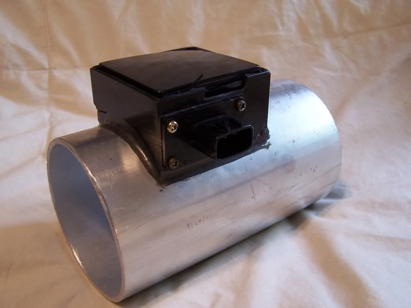
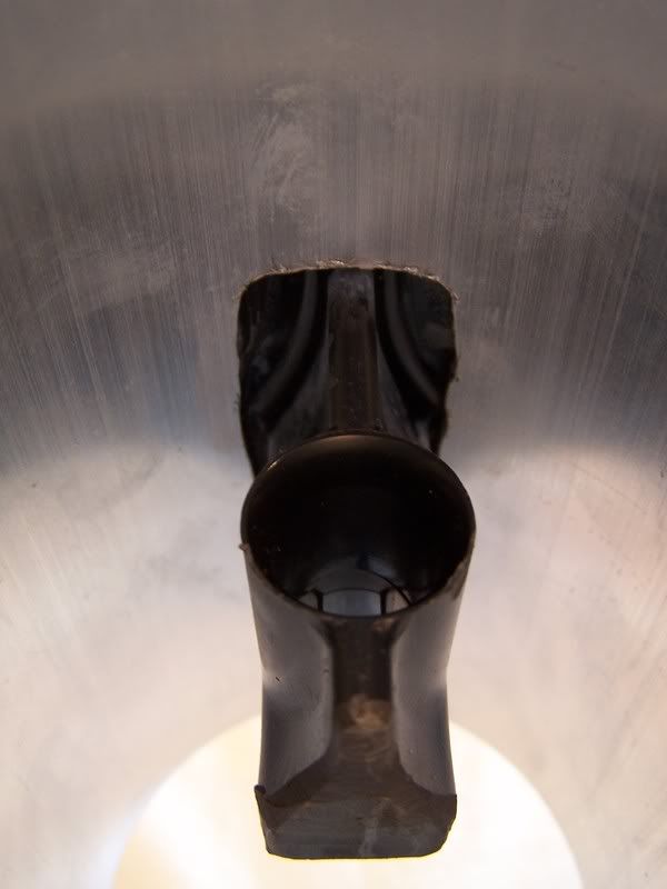
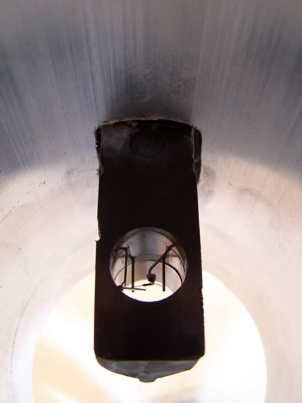
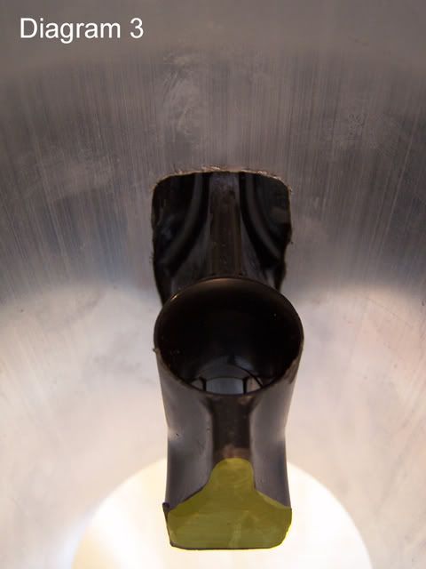
8. Set everything off to the side. Take your empty MAF housing and use a hack saw, saw zaw or other appropriate tool to cut plastic to make your cuts. I just did mine flush with the walls of the housing(seen is diagram 1). I then cut the sensor post from the inside of the housing. (yellow highlight, seen in diagram 3)
9. For me, this was the longest part. I am a perfectionist. What happens is, since the diameter of the black MAF tube was smaller than the large one, this means that the sensor housing will not sit nice and flush with your new tube. So I used a bench grinder to get the right shape. You can see where I grinding out, diagram 1, highlighted in pink.
10. Almost there, now just mark your hole on your new housing. I use an aluminum housing, PVC can cause harmful fumes, not to mention it doesnt resist heat well. I used a drill bit and a router to cut my hole. I just kept test fitting until it fit nicely.
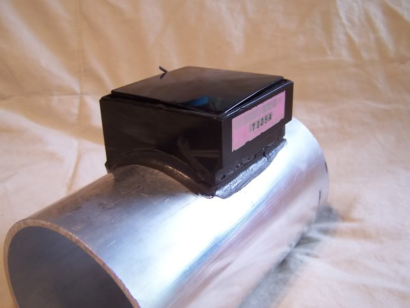
11. Last step. Use some super glue to secure the sensor housing to the new tube. Once it is dry, use liquid gasket, or similar, to make an appropriate seal around the edge.
Finally, just reassemble everything with caution, and don't forget to re-solder the plug so it will work!
1. Use a razor or exacto knife(#11 blade works well) to remove the seal around the edge of the cap. The seal is highlighted in blue on diagram 1.
2. Use the combination of a small flat head screw driver and your exacto knife to pry open the cap. You can see from the picture, I accidentally broke the wall of mine, this is no big deal as once I get it running, I am going to seal it back off with liquid gasket.
3. Remove the four outer screws on the plug itself. Be careful not to strip them, they arent easy. These are highlighted in red on diagram 1. DO NOT PULL ON THE PLUG!
4. Next, there will be a brass protector just under the plastic cap you just removed. It comes straight out, but may need some prying.
5. Here comes the harder part. You need to disconnect the main harness from the inside circuitry. The three contacts are highlighted in red in diagram 2. You have two options here:
a. The easy/fast yet risky way: Use a small flathead screw driver to break the 3 contacts to the plug from the leads off of the main circuit board. Just pry. They will come off. But too much stress and they will break. If they do, you will need to solder a new connection in.
b. The proper way: Simply use a soldering iron to heat up the solder joint, while using a small flathead to pry at the same time. No breaking, no risk.
6. Remove the three screws in the main circuit board. These are highlighted in orange in diagram 2.
7. Use a medium flathead to CAREFULLY! pry the main circuit board out of the housing. There is a rubber seal, and what I believe is locktite holding it in. Stick the screwdriver through the hole where the sensor plug came out of.
8. Set everything off to the side. Take your empty MAF housing and use a hack saw, saw zaw or other appropriate tool to cut plastic to make your cuts. I just did mine flush with the walls of the housing(seen is diagram 1). I then cut the sensor post from the inside of the housing. (yellow highlight, seen in diagram 3)
9. For me, this was the longest part. I am a perfectionist. What happens is, since the diameter of the black MAF tube was smaller than the large one, this means that the sensor housing will not sit nice and flush with your new tube. So I used a bench grinder to get the right shape. You can see where I grinding out, diagram 1, highlighted in pink.
10. Almost there, now just mark your hole on your new housing. I use an aluminum housing, PVC can cause harmful fumes, not to mention it doesnt resist heat well. I used a drill bit and a router to cut my hole. I just kept test fitting until it fit nicely.
11. Last step. Use some super glue to secure the sensor housing to the new tube. Once it is dry, use liquid gasket, or similar, to make an appropriate seal around the edge.
Finally, just reassemble everything with caution, and don't forget to re-solder the plug so it will work!


wow mohfpro90.. you went into great detail on your install.. all i did was cutout the brain from the old housing.. cutout the bottom from the old housing.. and drilled a big hole in my new (aluminum) 3"ID pipe, finished it off with a dremel and a cutting wheel.. made sure it fit and used some weatherstripping to seal it.. viola..
mowgli - your vafc2 will be fine for tuning this thing.. i havent made any corrections yet to it.. because i have the option on the safc2 (you dont) to tell it what MAF im using and what ECU im using and it converts the signal for me.. then after that i will (eventually) take it to a dyno and smooth out and a/f problems i might have.. now for yours.. since you have a vafc2 you will need to have it on the dyno before you install.. cause it wont run well enough to drive.. its going to through you waaay lean without any tuning.. but as for enough correction points using the vafc2.. dont worry.. you have more tuning points than me and many others who are running a larger MAF housing using a safc2.. goodluck with the install.. feel free to pm me if you need any help..
mowgli - your vafc2 will be fine for tuning this thing.. i havent made any corrections yet to it.. because i have the option on the safc2 (you dont) to tell it what MAF im using and what ECU im using and it converts the signal for me.. then after that i will (eventually) take it to a dyno and smooth out and a/f problems i might have.. now for yours.. since you have a vafc2 you will need to have it on the dyno before you install.. cause it wont run well enough to drive.. its going to through you waaay lean without any tuning.. but as for enough correction points using the vafc2.. dont worry.. you have more tuning points than me and many others who are running a larger MAF housing using a safc2.. goodluck with the install.. feel free to pm me if you need any help..

Thread Starter
Joined: Jul 2006
Posts: 1,172
From: St. Louis, MO
I thought about trying that, but my 4th gen IACV has to have somewhere to breath from between the MAF and TB. I may try something similar...who knows. I'll see what happens when I try the larger MAF.

Thread
Thread Starter
Forum
Replies
Last Post
TallTom
5th Generation Maxima (2000-2003)
57
Oct 14, 2025 05:16 PM
BPuff57
Advanced Suspension, Chassis, and Braking
33
Apr 16, 2020 05:15 AM