
3rd gen VQ35DE Full ECU Swap Progress Thread
 02-15-2009 | 12:40 PM
#321

Update:
Just this past Wednesday, I had Surra_TT come over so we could test a new NWP product for the 5.5 gen. After we were done, I pulled out my complete wiring harness for this VQ35 swap project. I start going over it and labeling different connectors as I compared it to his 2K2 Maxima harness. Then, we quickly find out that something isn't right. There are just too many major differences between the connectors. So I said, "oh well, I'll figured it out" and we gave up since it was getting late. The harness did not seem like the right one though.
Then, Surra had an epiphany and sends me a text that says "Your harness is a 4cyl Altima!!!!!!". I open up the QR25DE 2K3 Altima FSM and start comparing wire colors and sure enough, he is correct! The stupid salvage yard said the harness came from a 2K3 Maxima 3.5, but it actually came from a 2K3 Altima 2.5L. I guess they couldn't tell the difference between an Altima and Maxima and a 2.5L and 3.5L.
But, I have a lead on an intact harness from another 5.5 gen auto. So I will post pics just as soon as I get this one.
02-16-2009 | 11:06 AM
#322
Thread Starter
NWP Engineering.com
iTrader: (128)
Joined: Jul 2001
Posts: 14,066
From: Walstonburg, NC
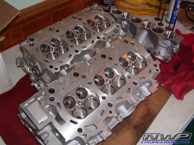
I have been busy lately knocking out some of this headwork! Here are some pics of the LIM and RH head intake ports all scribed and ready to go. The intake ports are matched up perfectly with the 1/16" thick NWP Engineering Thermal Intake Spacer, but port matched to the port size of the OEM gasket. Port matching to a 1/16" spacer instead of the stock thin gasket is a little tricky since it slightly raises the level of the LIM on an angled V6 head. But it's perfect.
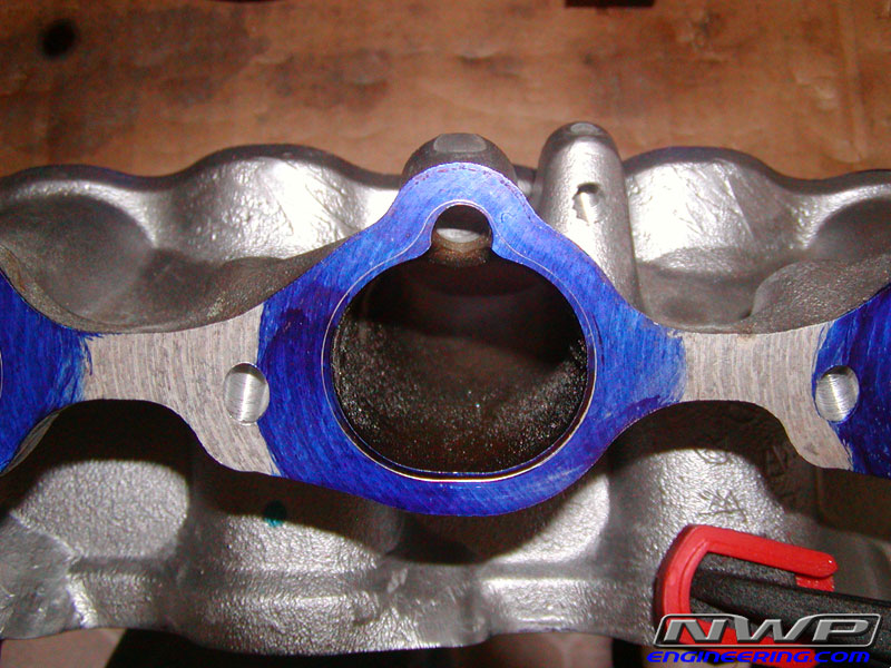
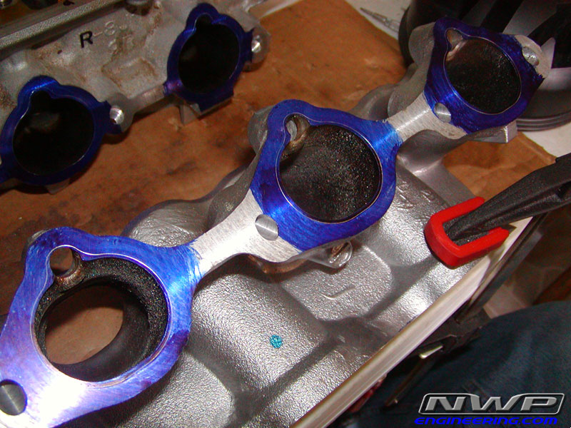
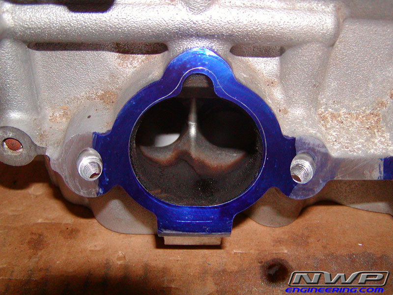

The LIM is now 100% completed as well as the LH head. I have started on the RH head and finished all the intake ports. Now I just have about 8 more labor hours left on the intake valves, exhaust ports and valves, and then combustion chamber polishing. Once the headwork is complete, I will start making actual progress.
The LIM is now 100% completed as well as the LH head. I have started on the RH head and finished all the intake ports. Now I just have about 8 more labor hours left on the intake valves, exhaust ports and valves, and then combustion chamber polishing. Once the headwork is complete, I will start making actual progress.
02-16-2009 | 10:21 PM
#323

sweet! so what's the blue stuff for? and where it looks like you sort of etched a shape into the blue stuff, is that what you're shaping the ports to (the "scribing" i assume you were talking about)
02-17-2009 | 06:47 AM
#324
Thread Starter
NWP Engineering.com
iTrader: (128)
Joined: Jul 2001
Posts: 14,066
From: Walstonburg, NC
That's Dykem layout fluid. It makes the scribe marks easier to see. I scribed around the stock OEM intake gaskets and I matched both intake ports to that (heads and LIM).
02-17-2009 | 03:24 PM
#325
i see.. so why did you use the OEM gasket as a template rather than one of your spacers? or did i read something wrong?
02-17-2009 | 03:48 PM
#326
Thread Starter
NWP Engineering.com
iTrader: (128)
Joined: Jul 2001
Posts: 14,066
From: Walstonburg, NC
The ports on the heads are larger than the ports on the LIM. And the OEM LIM gasket is oversized and is not matched to either the LIM ports or the ports on the heads. So this is a good template to use since it's larger than both LIM and the ports on the heads.
As for the port work I will do on the UIM, I will use the spacers to scribe all my lines since it's already matched perfectly to the large of the two ports (the LIM). All I'll have to do then is port matched the UIM runners. When I ported the upper part of the LIM, I didn't increase the size of the port. I just decreased the initial angle at the top part of the runners and polish everything up. If you've ever seen a VQ35 LIM, you'll know what I mean by decreasing the angle.
02-27-2009 | 06:46 PM
#327
Thread Starter
NWP Engineering.com
iTrader: (128)
Joined: Jul 2001
Posts: 14,066
From: Walstonburg, NC
It's been a little while since my last update. I've been slacking off a little bit with the pictures.
Several posts above, you may have read that I got the wrong engine harness. Well I fixed that problem rather quickly! The harness came off an 03 Maxima AT. I also snagged the alternator and MAF from the same car.
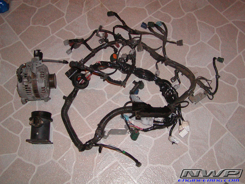
And look what just arrived today!
Several posts above, you may have read that I got the wrong engine harness. Well I fixed that problem rather quickly! The harness came off an 03 Maxima AT. I also snagged the alternator and MAF from the same car.
And look what just arrived today!
02-27-2009 | 06:51 PM
#328
Thread Starter
NWP Engineering.com
iTrader: (128)
Joined: Jul 2001
Posts: 14,066
From: Walstonburg, NC
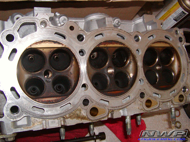
Also, just this evening, I FINALLY finished all the headwork that I have to do!!!
27 labor hours of back breaking tedious work broken up over the period of several months. I kept a strict timesheet so I knew how much time I was spending on each task. The 2nd head went a lot faster of course since I already mastered my techniques on the first head.
I will get my heads resurfaced next week and immediately start assembling the heads and installing all my goodies from DaveB!
After that, I have to do a little grinding on the coolant entry port on the block in order to install the HR head gaskets.
I am so relieved that all this headwork is finally over with! Onto the fun stuff!
02-27-2009 | 06:53 PM
#329
oh good, the harness. So are you just gonna cut your VE harness open and take the TCU wiring out of it, or are you gonna hand-wire all that?
also...
in for before/after pics of the headwork
also...
in for before/after pics of the headwork
02-27-2009 | 07:01 PM
#330
Thread Starter
NWP Engineering.com
iTrader: (128)
Joined: Jul 2001
Posts: 14,066
From: Walstonburg, NC
The VE engine control harness is coming out. I haven't completely decided what I am going to do with the VE TCU wiring. I could just get a Suprastick and call it a day. But for right now, I am going to prune as much wiring out of the car as I possibly can to save weight. I planned on keeping the VE TCU and needed wiring. There's no need for me to run any custom wires and make connectors. The harnesses are all I need pretty much.
02-27-2009 | 07:34 PM
#331
You've already seen my port work pics.
The VE engine control harness is coming out. I haven't completely decided what I am going to do with the VE TCU wiring. I could just get a Suprastick and call it a day. But for right now, I am going to prune as much wiring out of the car as I possibly can to save weight. I planned on keeping the VE TCU and needed wiring. There's no need for me to run any custom wires and make connectors. The harnesses are all I need pretty much.
The VE engine control harness is coming out. I haven't completely decided what I am going to do with the VE TCU wiring. I could just get a Suprastick and call it a day. But for right now, I am going to prune as much wiring out of the car as I possibly can to save weight. I planned on keeping the VE TCU and needed wiring. There's no need for me to run any custom wires and make connectors. The harnesses are all I need pretty much.
with suprastick is it still usually fully-auto until you enter manual mode, like newer cars have? My main worry would be the interconnecting wiring between the ECU and TCU (on the stock VE stuff), and if it's the same pinout onto the 3.5 ECU.
02-27-2009 | 09:37 PM
#332
In an auto A33B, the TCM and ECM communicate using the two wire CAN system. You will not be able to interface the TCM from an A32 or earlier vintage max with it.
02-27-2009 | 09:47 PM
#333
03-01-2009 | 04:49 AM
#335
yea, i was looking at that.. but if the sensors on both transmissions read the same way, then he can probably just get the a33b TCU and splice a his harness connectors (unless of course they plug in exactly the same way! that would be cool) onto that, cuz they have the same control mechanism (a/b solenoids, overrun clutch, tc lockup, line pressure solenoid) on both trannys.
03-01-2009 | 07:02 AM
#336
yea, i was looking at that.. but if the sensors on both transmissions read the same way, then he can probably just get the a33b TCU and splice a his harness connectors (unless of course they plug in exactly the same way! that would be cool) onto that, cuz they have the same control mechanism (a/b solenoids, overrun clutch, tc lockup, line pressure solenoid) on both trannys.
03-01-2009 | 03:29 PM
#337
Thread Starter
NWP Engineering.com
iTrader: (128)
Joined: Jul 2001
Posts: 14,066
From: Walstonburg, NC
I got the 03 alternator just b/c my VE alternator won't bolt to the VQ block/timing cover.
Thanks.
03-01-2009 | 07:56 PM
#338
yea i meant that if he gets the a33b tcu and just wires the outputs to work on his 3rd gen tranny... he is doing the full 5.5 ECU swap, he's using the drive-by-wire throttle, so if he uses the TCU form the 5.5 as well, it's basically using EVERYTHING from the 5.5, except that the outputs are controlling a slightly different tranny. I looked, and the output plugs are not exactly the same.. but with about an hour or two spent comparing FSMs, it should be pretty easy to cut and splice (or do the pin-release-and-relocate method like i did for my 5spd swap re-wire) to get the right wires going to the right plugs on the tranny case.


 03-05-2009 | 09:44 AM
#344
Thread Starter
NWP Engineering.com
iTrader: (128)
Joined: Jul 2001
Posts: 14,066
From: Walstonburg, NC
I have a little bit of a problem and I may be worrying over nothing. But the machinist said he took off 4 thousandths. I took several very accurate head height measurements at various points around the heads. It turns out that the machinist removed an average of .004" on the intake side of the heads. But on the exhaust side of the heads, he removed anywhere from .006 to .009". I did my homework before choosing this machinist. He's widely considered to be the best machinist in the area when it comes to building race engines over 1500 hp.
But, what issues could I possibly run into if he did remove .009"? The block hasn't been touch BTW. And the overall height of the head is .004" below what the FSM says is in spec. It was on the low side of things to begin with.
I am pretty sure piston to valve clearances aren't going to be an issue. I am going to use the HR head gasket, which is not really any thicker than stock. And I have the 10.9mm lift cams from ebay.
But what issues could I run into if .009" removed is too much?
03-06-2009 | 03:50 PM
#345
Thread Starter
NWP Engineering.com
iTrader: (128)
Joined: Jul 2001
Posts: 14,066
From: Walstonburg, NC
I did some more math on these heads. I figured up the amount they are crooked or sloped. I took several measurements on the intake side and the exhaust side of the heads. It turns out that the machinist took a lot more off the exhaust side of the heads. Below is the difference between each side of the heads. You will see the stock head decks are very close to parallel with the valve cover gasket surface on the top of the head.
STOCK LH Head variance: .00160"
STOCK RH Head variance: .00090"
Milled LH Head variance: .00075"
Milled RH Head variance: .00550"
So the stock heads are flat within a couple thousandths, which is pretty good. And the Milled LH head is good since it's below a thou. But take a look at the RH head, which is over 5 thousandths. That is roughly the width of a normal piece of copier paper, which shouldn't make a difference, but can anybody think of anything that could be affected b/c of this?
Also, my question above still stands. If anybody has any thoughts that may sound crazy and you don't want to post, please PM me and tell me what you think. Thanks.
03-06-2009 | 04:31 PM
#346
Did you bring in to question with the machinist the results of your measurements? What is his stance on this?
How does one find out what is generally accepted as being within a tolerable limit and what isn't?
How does one find out what is generally accepted as being within a tolerable limit and what isn't?
03-06-2009 | 06:05 PM
#348
Thread Starter
NWP Engineering.com
iTrader: (128)
Joined: Jul 2001
Posts: 14,066
From: Walstonburg, NC
I spent a couple hours at the junkyard today snagging some parts for a prototype for a new 02/03 Maxima NWP product. I also picked up an ignition switch connector with wiring since I want to use the 02 Maxima key and ignition to start the car. I don't know what it is, but I really want to start my 3rd gen with a newer ignition switch.
I also snagged some relays I needed with sockets and wiring, an ECU mounting bracket, and a clock that I may use some day. Who knows.
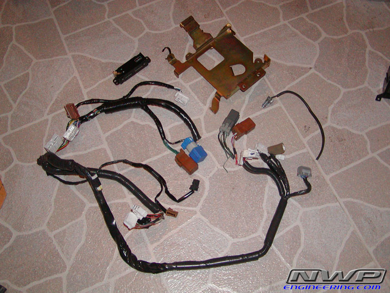
I also snagged some relays I needed with sockets and wiring, an ECU mounting bracket, and a clock that I may use some day. Who knows.
03-09-2009 | 08:47 AM
#349
Thread Starter
NWP Engineering.com
iTrader: (128)
Joined: Jul 2001
Posts: 14,066
From: Walstonburg, NC
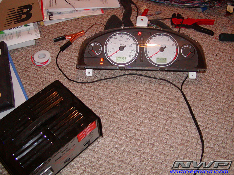
I messed around with my instrument clusters a little bit today. The cluster I want to use shows 49K miles on the odometer and came from the same car my engine came from. So it would be nice to see the actual miles of my engine since I didn't do a full rebuild.
But, that cluster has black face gauges and another cluster that I have has silver gauges which look much nicer. So in order to keep the right miles, I swapped face panels successfully. It was a bit scary at first not knowing if I will mess up my calibration which I've heard so much talk about it on the forums. But I discovered there is a calibration mode on the cluster for the 5th gen digital odometer. The steps are in the FSM. Once you are in this mode, the needles point to a certain spot (i.e. Speed=24mph, RPM=1300, etc). You note where the needles point to before you remove them. And removing the needles without breaking anything seems a bit tough as well. But I managed to do the swap successfully the first time. You just gotta be really careful while prying up on the needle for it to pop out without breaking anything.
Giving 12v to the right terminals and providing a ground:
Swapping panels:
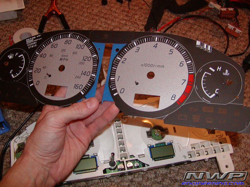
Last edited by Aaron92SE; 03-09-2009 at 08:50 AM.
03-09-2009 | 10:10 AM
#351
Thread Starter
NWP Engineering.com
iTrader: (128)
Joined: Jul 2001
Posts: 14,066
From: Walstonburg, NC
All I know is that my heads were flat before and now the RH head isn't. I'm just want to make sure a 5 thou slope isn't going to affect anything. I also want to be certain that removing as much as 9 thou from a head that was already very low on the in-spec nominal head height range won't give me any problems.
Any thoughts?
03-10-2009 | 08:33 AM
#354
Thread Starter
NWP Engineering.com
iTrader: (128)
Joined: Jul 2001
Posts: 14,066
From: Walstonburg, NC
I hope to have the engine in the car by early April. It depends on how fast I can get this engine back together now that the headwork is done.
The NWP Engineering web server seems to be working just fine. Are you still having problems seeing the pics? Is anybody else having problems?
 03-10-2009 | 02:38 PM
#359
Thread Starter
NWP Engineering.com
iTrader: (128)
Joined: Jul 2001
Posts: 14,066
From: Walstonburg, NC
No. I haven't been able to find an answer to my questions above. So I don't want to assemble my heads until I have some idea on the problems I may face with the head resurfacing issue.
The headwork itself isn't an issue though. That's perfect, cause I did it. But the head resurfacing is the issue.
The headwork itself isn't an issue though. That's perfect, cause I did it.
But the head resurfacing is the issue.
03-10-2009 | 04:42 PM
#360

Senior Member
Joined: Nov 2006
Posts: 539
No. I haven't been able to find an answer to my questions above. So I don't want to assemble my heads until I have some idea on the problems I may face with the head resurfacing issue.
The headwork itself isn't an issue though. That's perfect, cause I did it. But the head resurfacing is the issue.
The headwork itself isn't an issue though. That's perfect, cause I did it.
But the head resurfacing is the issue.