
Sprayed for the first time, got some questions


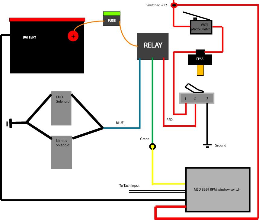
I see something very wrong here ?? - the FP switch is controlling the Gnd (BLK) connection of the MSD RPM switch. This means that the MSD is not powered up until the WOT switch is activated, and that takes a few seconds before it works.
The black wire from the MSD should go directly to a battery ground, and the WOT switch should go to switched battery + , through the FP Switch , to the arming switch +12v connection.
Nice diagram, though....
The black wire from the MSD should go directly to a battery ground, and the WOT switch should go to switched battery + , through the FP Switch , to the arming switch +12v connection.
Nice diagram, though....
think i might take the time to make this look good at some point for general reference. Going to be doing my own nitrous instal hopefully around christmas


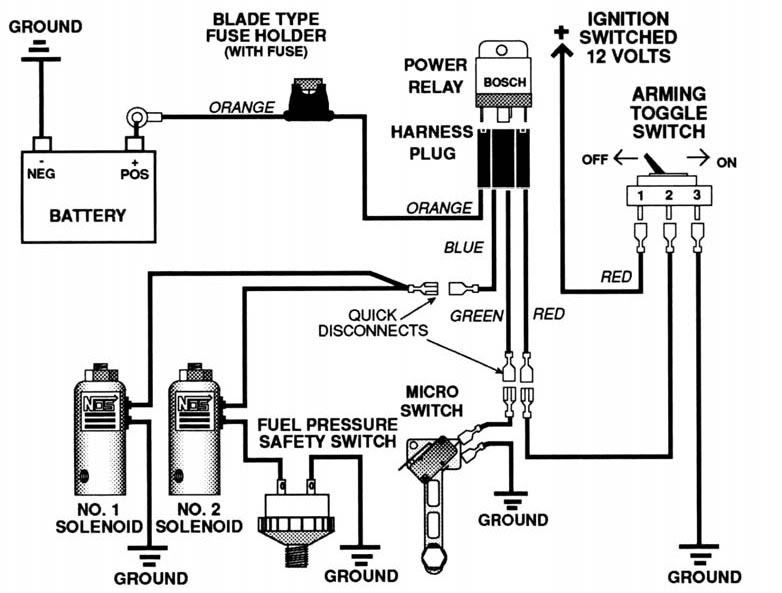
FPSS is only to be used to cut ground. It can't handle any charge. Wire it inbetween the red wire going from the toggle switch to the relay.
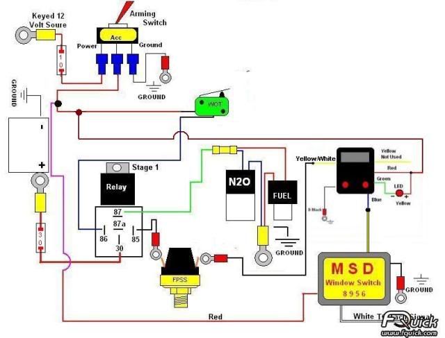
Or just look at my earlier post. I have a diagram made out that should work.
Or just look at my earlier post. I have a diagram made out that should work.
Last edited by 2002AltimateV6; Nov 3, 2009 at 07:56 PM.
edit: Here's the diagram
Part of the reason we had the kit wired the way we did, initially, was due to the length of the connectors and wires already present in the kit that just seemed to fit into the car (minus a few odds and ends for the arming switch). Now don't get me wrong, I do agree that having that switch be subjected to those currents would/could lessen the life of the switch. Grant is going to be getting the Dynotune A/F safety cut-off switch here very shortly when he gets a LC1 wideband.
Last edited by Mad-MAX_SE; Nov 3, 2009 at 08:10 PM.
Originally Posted by Dynotune
NOTE: The switch is a low current switch, running high current devices like solenoids directly through the switch
contacts will destroy the switch and void your warranty.
contacts will destroy the switch and void your warranty.

http://i2.photobucket.com/albums/y41...2192592A-1.jpg
This should work for your setup.
I believe this should work for when you get the lean/rich shut off switch. Can someone verify?
Last edited by 2002AltimateV6; Nov 3, 2009 at 08:56 PM.

I have my system wird alittle different but the concept is all the same. I have the niod hard wire directly to the battery and the relay providing ground
And with my progressive nitrous control is does not samething it adds and removes ground but that part does not matter cause a relay will do whatever you tell it
but any of the diagrams will work fine
And with my progressive nitrous control is does not samething it adds and removes ground but that part does not matter cause a relay will do whatever you tell it
but any of the diagrams will work fine
My dual-stage has a lot of tricks - and the diagrams would be confusing, so I'll skip mine. You should know that energizing the solenoid pair can create a voltage spike that can reset the MSD, which takes a while to reboot. I have large electrolytic capacitors across each solenoid relay to absorb the spike. I use a WOT switch for the first stage and a floor switch for the second stage. There's more, but there's lot of bitter experience in there...
You sure stirred up a lot of interest in nitrous wiring diagrams! never saw so many in one thread.......
Last edited by grey99max; Nov 4, 2009 at 07:32 AM.


DO NOT DO BUSINESS WITH THIS MEMBER - OWES PEOPLE MONEY
iTrader: (7)
Joined: Jan 2008
Posts: 3,468
From: Greensboro, NC
 I have a DynoTune Two Stage RPM Window Switch / TPS for sale for $60 shipped. Here's a link http://www.dynotunenitrous.com/store...?idproduct=194

Thread
Thread Starter
Forum
Replies
Last Post
max_speed97
5th Generation Classifieds (2000-2003)
2
Aug 26, 2015 07:46 PM
homewrecker
5th Generation Maxima (2000-2003)
13
Aug 24, 2015 08:56 PM
doobadoo
4th Generation Maxima (1995-1999)
2
Aug 15, 2015 06:43 PM
jchronis2552
4th Generation Classifieds (1995-1999)
0
Aug 13, 2015 07:48 AM