
Installation Instructions / How-To's / FAQ's / Product Reviews


Senior Member
Joined: Aug 2002
Posts: 1,067


Newbie - Just Registered
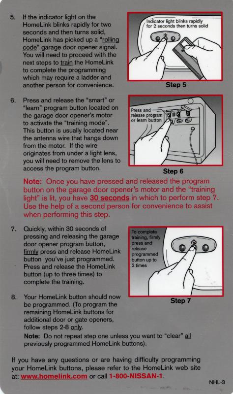
Joined: Mar 2003
Posts: 5
I have used Fat-Mat from fatmat.com. I got the material on ebay though. Costed $50 for 36 sq ft and it seems to do the job and stick well to anything!
Anyone have any other experiences with it?
Go there and search in their forums. Search for High Temp Mastic or dynamat and see what you come up with. There is a company you can get the same stuff just without the dynamat screenprint on it for about half the price.
Nevermind found it for you
http://www.mcmaster.com/
HI-TEMP MASTIC, its all the way at the bottom, it costs around $13 for a 32" X 54" sheet.
more detailed instructions...
go to the search box on mcmaster.com
type in acoustic
go to acoustic dampers
(you will need adobe acrobat viewer)
there you go at the bottom.
Hope this helps and do it yourself! You'll appreciate it more that way
http://forums.maxima.org/showthread.php?threadid=27094 [/B][/QUOTE]


Senior Member
Joined: Apr 2002
Posts: 702
Originally posted by Y2KevSE
OSCAI (Ooglie Stock Cold Air Intake) write-ups
punkdork's:
http://punkdork.net/max/oscai.htm
mdeal's:
http://www.fourthrock.com/maxima/oscaiinstall/
Paul2kGXE's:
http://paulwendy.com/maxima/svcai.htm
OSCAI (Ooglie Stock Cold Air Intake) write-ups
punkdork's:
http://punkdork.net/max/oscai.htm
mdeal's:
http://www.fourthrock.com/maxima/oscaiinstall/
Paul2kGXE's:
http://paulwendy.com/maxima/svcai.htm
http://forums.maxima.org/showthread....hreadid=202160

Here is the How-To on how to take apart your new 15.5" clear spoiler light and paint over the ugly brown circut board.
http://maxima.cardomain.com/member_p...=211310&page=8
http://maxima.cardomain.com/member_p...=211310&page=8

Senior Member
Joined: Feb 2002
Posts: 1,322
For some of old How To instructions, go here.
http://www.max-world.org/frames/howtodo.html
http://www.max-world.org/frames/howtodo.html
Bandwagon Lover

Joined: Feb 2002
Posts: 1,023
Replacing power steering belt
http://forums.maxima.org/showthread....highlight=belt
I replaced this belt this weekend and I will like to share some info withyou guys.
This is not a difficult task....I would rate it 3 out of 10. But it does take me the entire day because I wasnt prepared for it. Initially, I wanted to clean out some shredded belt before my 2.87 pulley install. But then I saw the powersteering belt got shredded from 4 ribs to 2....so I decided to replace it. Totally unprepared. I use Nissan service manual and Haynes. 4th gen is different than 5th gen.
Objectives:
1.loosen main drivebelt
by FIRST loosening the nut that holds your idler pulley and then reduce the belt tension with the tension adjuster. If the nut is not loosen first, you might snap your tensioner adjuster.
2.loosen the bolt at the back of the powersteering pump
This is hard. The 14mm bolt is located near the rear exhaust manifold and it's really hard to get to. I use the universal joint along with extension to loosen it a little bit. Then I use gear wrench to take care the rest.
 universal joint
3.loosen the belt tension adjuster lock bolt
Loosen the lock bolt a little bit, dont loose it all the way or you will regret for it.
4.adjust the belt tension with the adjuster bolt.
Turn it clockwise to lower the pump pulley. The belt will come loose. Counter-clockwise to raise the pump pulley when finish install.
belt tension adjuster and locking bolt
Random notes....
a.you have to remove your wheel
b.do this when your car is cold or the exhaust manifold will burn you.
c.dont loosen the lock bolt all the way or the tension adjuster is going to come off. It took me 1 hour to put it back.
d.gear wrenches helps a lot in this job and saves a lot of time. I use them to loosen all the bolts.
e.FYI : old belt, in several pieces
f.choosing a new belt: recommanded to use Pep boy's Dayco belt if the OEM is not available. The finish is similar to that of the OEM.
STUDMAN's SRS Airbag Light Reset Trick for 2000-2003 Nissan:
https://maxima.org/forums/off-topic/247172-who-grabbed-brazilian-marathoner-why.html
Note: Timing is KEY, use a stopwatch if you have to.
1) Turn IGNITION on (but don't start car)
2) After the AIRBAG warning lamp lights for 7 seconds and then goes out, turn IGNITION off within 1 second.
3) Wait 4 seconds
4) Turn IGNITION on (but don't start car)
5) After the AIRBAG warning lamp lights for 7 seconds and then goes out, turn IGNITION off within 1 second.
6) Wait 4 seconds
7) Turn IGNITION on (but don't start car)
8) After the AIRBAG warning lamp lights for 7 seconds and then goes out, turn IGNITION off within 1 second.
9) Wait 4 seconds
10) Turn IGNITION on (but don't start car)
11) Wait 3 seconds
12) Turn IGNITION off
13) Wait 2 seconds
14) START Car
15) Turn IGNITION off
16) Wait 2 seconds
17) START Car
AIRBAG warning lamp should blink for 7 seconds and then go out and never come back on. If it does, then you have a problem.
How-To RESET the Nissan Vehicle Immobilizer System(NVIS) on a 2K-2K1
Once a BAD key has been used CONSECUTIVELY five or more times to unsucessfully start the engine, the ECU enters "LOCK MODE".
If the ignition key is in the "ON" position and the security indicator LED(on the clock) is ON(doesn't blink), the NVIS is triggered by one of numerous possiblities but it's probably the chip in the key.
There are TWO possible solutions:
1)Try to escape from LOCK MODE,MUST USE A GOOD KEY and perform the following:
a.Turn ignition switch to "OFF".
b.Turn ignition switch to "ON" with GOOD key.(Do NOT start engine.) Wait 5 seconds.
c.Return key to "OFF".
d.Repeat steps b and c TWICE(total of three cycles).
e.Start the engine.
2)If 1) didn't work it MUST be towed into Nissan to have ALL the keys wiped and reprogrammed with the ECU.
2002+ SES/MIL and ECU Reset Procedure
This is how to reset all the stored SES/MIL codes in the ECU, as well as resetting all the learned settings in the ECU. Note that it takes between 100 and 200 miles AFTER the reset before the ECU will adapt to your driving style.
This procedure is also helpful in retrieving the stored error codes without the use of an ODB-II scanner. Just follow steps 1-4 and the SES light will flash with a code. The code will be 4 digits long. A "0" is ten flashes. The SES light will pause between digits. If there are multiple codes stored, the SES light will flash the first code, then second, then third... and repeating again at code number 1.
http://maxima.theowensfamily.com/ecu.asp
[edit]
!!!!!WARNING...Make sure the engine is NOT running...WARNING!!!!!
[/edit]
CREDIT: studman
http://www.technosquareinc.com/350reset.htm
ECU Reset Procedure for 2K2+
Accelerator Pedal Release Position Learning Procedure for 2K2+
Throttle Valve Closed Position Learning Procedure for 2K2+
Idle Air Volume Learning Procedure(Throttle Position Learning Procedure) for 2K2+
Credit: technosquareinc.com
Idle Air Volume Learning Procedure for 2K2+...FSM version with graphic:

Idle Air Volume Learning Procedure for 2K-2K1 withOUT Consult-II Tool
MAXSPEED SPRING INSTALL HOW-TO:
detailed how-to with pics for installing MaxSpeed (and any other brand) springs on a 2k-2k3:
http://www.kevinfisher.net/web_server/maxima/springs
Here is the GAB using a coat hanger and not destroying your expensive air filter holder. You can find it here on the org at:
http://forums.maxima.org/showthread.php?t=266911
or at my website:
http://home.insightbb.com/~dwh/GAB.htm
Well here it is. The How-To on installing heated sideview mirrors on your 5th gen. May work on 4th but dont know about that. It's at this link below:
http://home.insightbb.com/~dwh/mirror.htm
Hope this helps you guys out.
-Dave Honey aka Fezzik
Pro-Fit VSM Bracket Install
First of all, even though the Pro-Fit VSM (Vehicle Specific Mount) only says it's for '00-'02 Maximas, it fits the '03 fine (I figured it would, there is zero difference between the 02 and 03s). This mount is designed for mounting cell phones, but can be used for a ton of things including GPSrs and Satellite Radio portables. Keep in mind that the mount itself is fairly stubby, so if you don't want your radio controls covered up (i.e. you're mounting something other than a cell phone), you'll want to also buy the generic extender plate from Pro-Fit.
However, for anyone considering this install, I hope you're a very patient person. It took me THREE HOURS to do it, and had I known what I was in for I would have taken pictures. There are a few links around the internet (including some on maxima.org) that explain how to do the install, but none of them cover everything I had to do. I'm typing this up to hopefully save someone a ton of time. Additionally, even though pictures would be helpful, you really don't need them. Without further ado...
1. Use the Pro-Fit install instructions as TP or to start a bonfire. They are the most useless, horrid instructions I have ever read in my entire life. Not only that, they're misleading and will cause you to scratch the hell out of your air vents/console if you follow them.
2. You will need a drill with 5/64" bit (or similarly tiny bit should work, you just need to get a tap for the screws started), beefy Philips screwdriver, very skinny flathead screwdriver, beefy flathead screwdriver, the brightest flashlight you can find. Pro-Fit says you need hook tools, but the tolerances in the clips are so tight, they're utterly useless. I did use mine to prop things open, but a screwdriver does the same job just fine.
3. Do one of two things. Either put your parking brake up and then move the tranny to 4th (or 3rd if auto), or just unscrew the boot. I did both, but it's probably unnecessary (I have an auto, BTW). Then, open the ashtray and remove the insert. Remove the Philips screw behind it.
4. Here's where the real fun begins. There are four clips holding the ashtray/shifter bezel in. You will be pulling off the entire piece of gray plastic that surrounds the shifter, and goes up to the HVAC unit. The four clips are located two in front of the shifter, two in back. If you drew an 'X' through the top of the shifter, the clips are located where the "X" hits the edges of the bezel. This is helpful in knowing where to pull. Yes, pull, because unless you want to shred your console you're going to just yank this thing out.
5. Take the skinny flathead screwdriver and stick it into the area between the bezel and padding at the backmost area of the bezel that is the closest to the armrest. Do this very slowly, and gently. It will take some time to do this right. Now, you should get yourself a small gap, which is good for sort of working the screwdriver back and forth to loosen the back end of the bezel. Once a gap starts to form, use the beefy flathead to speed things up. You can stick a screwdriver in there about 4" or so before you start hitting important things. Use the flashlight to get your bearings here. Now, using the beefy flathead get yourself just enough room to slip a few fingers underneath. If you hear something "pop" this is good, that means you undid one of the rear clips. Get both sets of fingers underneath the whole rear of the bezel and lift SLOWLY. You will have to exert what seems an unnecessary amount of force, but the two rear clips should POP with authority. Now, grasp the whole rear of the console and lift, and the two front clips should pop. Now, SLOWLY AND CAREFULLY, lift the bezel over the shifter (you will have to get underneath the lip of the HVAC unit, just tilt the whole mess up slightly) and let it hang into the driver's footwell. Don't disconnect any wiring. I have heard of people breaking clips doing it this way, so if you don't have the guts just have a pro do this. Anyway, the key to NOT breaking clips is to lift EVENLY back-to-front and don't lift the back end too high up while the two front clips are still engaged.
6. The amusing thing is that wasn't even the hardest part!
7. No, that time is now. OK, take out the two philips screws behind the now-removed bezel that you see that hold up the center stack. There is a screw in the middle, you can ignore this one. Take the skinny flathead in one hand, and with the other hand GENTLY grab underneath the HVAC unit and lift straight up. You will notice that the top air vents now overhang the radio by a few millimeters. Now, take the skinny flathead and put the tip in the middle of the overhang and release the stack. Now, you will see the tip of the flathead is now seperating the air vents and radio. OK, get the beefy flathead ready. Lift the center stack again, and you'll see a larger gap develop right next to the skinny flathead. The key is to get the beefy flathead PAST the lip in between the radio and the vents - this lip is normally invisible. At some point while doing this you should hear a familar POP. This is the two lower clips that hold the air vent unit in place releasing. Hurray, now the hardest part of the whole procedure.
8. With the beefy flathead in place (which is keeping the bottom clips from going back in place), look at the two air vents in the air vent unit and get ready to do battle. Do not hurry through this part, or you will have a repair bill from your friendly local Nissan dealer. Make sure both vents are open, and feel at the bottom of one of the vents. You will feel a little lip there. Put all four fingers as far into the vent as you can, and try to get a good grip. I'd like to reiterate that you're getting a grip at the VERY BOTTOM of the vents, right beneath the bottommost "blind". Do not even try to get a grip on any of the blinds or other delicate plastic parts inside of this thing. Ok, take your other hand and put that one at the bottom of the other vent. Now SLOWLY PULL. You won't even feel the thing begin to give. You're going to have to pretend you're trying to pull a lead toilet. All at once, there will be a terrific CRACK as the whole air vent unit gives way and comes out. The screwdriver will fall out, it might not be a bad idea to wear eye protection in case it goes along for the ride.
Technically it is probably possible to break the clips, but once you see the side clips holding this sucker in you'll realize you were an idiot for thinking this. They are SOLID, and regardless of what Pro-Fit says are absolutely impossible to somehow "release" and get the thing out with a minimum of force. That is BS.
9. If you get this far, you can figure the rest out. Unscrew the two phillips screws that were underneath the air vent unit, and VERY CAREFULLY take the whole center stack out and rest it on the center console. Look towards the right side of the cavity and you will see a square hole that is roughly where the middle of the radio was. About an inch or so beneath this, test-fit the bracket - make sure the mounting holes aren't directly behind some wire, you are fairly close to some. It should fit perfectly (hence the whole "VSM" concept). Hold it there, and use one of the screwdrivers to scratch up the plastic where the mounting holes in the bracket are. Or use a pen, whatever. Drill, screw the thing in place (don't overdo it, you are screwing into plastic and can easily strip the hole!), and then reverse the directions to put Humpty back together again.
10. I have the Audiovox Sirius PNP2 Jampack, so I had two options. Either you can buy the extender plate from Pro-Fit and screw the cradle right into that, or you use the included Audiovox mobile mount and mount THAT to the Pro-Fit mount. If you're going to do that screw the left half of the Audiovox mount (the winged thing with 3M tape on the back), and then just bend the "wings" around the Pro-Fit mount. This will look slightly ghetto compared to buying the Pro-Fit extender, but that's ok. I say "will look" because currently I only have the Pro-Fit installed. My hands were hamburger by the time I had this thing installed last night (it didn't help that I had to figure out my own instructions!), and I didn't have the patience to complete the install.
For the record, I hate Nissan for making cars with such tight tolerances and a "leatherette" dash (which looks nice but you can't use the 3M stuff on it), I hate Pro-Fit for writing the world's worst instructions, and I hate Sirius for having such an awesome service that made me want to go through such extremes to enjoy their programming in my car.
Hope this helped somebody! If you have any further questions please PM me.
Replacing Stock Automatic Transmission Pedals With 20th Anniversary Edition Pedals
Here is my write-up for replacing your stock automatic transmission pedals with the 20th Anniversary Edition pedals. Installation is relatively easy and shouldn't take one more than 20 minutes.
Good luck. Peace.
-----
TOOLS NEEDED:
- Very short flat-head screwdriver.
- Two strips of electrical tape.
INSTRUCTIONS:
1. Remove the stock brake pedal cover. This part is easy as it just peels away from the bottom.
2. Put on the AE brake pedal cover. Some people say it's a PITA, but if you do it this way, it may take less time:
- Massage the back rubber of the AE brake pedal cover with your fingers to warm it up a bit.
- Put the pedal cover over the metal pedal starting from the back. Just slide in the backside.
- Carefully work the upper rubber corners over the pedal.
- With your fingers, take hold of all the front rubber lip of the cover and pull it forward. This should allow the cover to fit over the front of the pedal.
- Carefully work the lower rubber corners over the pedal.
- Done!
3. With the flat-head screwdriver, carefully remove the black plastic piece that locks the AE pedal to the accelerator assembly main bar. Remove the AE pedal completely from the bar.
4. Using the flat-head screwdriver, carefully remove the stock accelerator pedal from the accelerator assembly main bar. Work the screwdriver head from the upper-left side of the pedal and the plastic lock will eventually give and open. Remove the stock pedal completely from the bar.
5. Note that the AE accelerator assembly main bar has two pieces of heat-shrunk tape applied to it. Wrap two strips of electrical tape at the same locations on your accelerator assembly main bar.
6. Put the AE pedal on your accelerator bar. The electrical tape should eliminate any kind of 'looseness.' Put the black plastic piece back on to lock the AE pedal to the bar.
7. Enjoy your new pedals.
COMMENTS:
- If you purchased your AE accelerator pedal from CourtesyParts.com, they sell you the entire assembly which includes the pedal and bracket. However, all you need to do is remove the stock pedal, use two strips of electrical tape, and put on the AE pedal.
- If you want to really complete the look of the new pedals, consider getting the 350Z 'dead pedal' foot rest. It matches the 20th Anniversary Edition Maxima pedals and is very inexpensive. It does, however, require a bit of modification as part of its plastic assembly needs to be cut/sawed off. The end result, however, is very nice.
- This write-up is for '00/'01 Maximas. Since '02/'03s switched to an electronic 'drive-by-wire' throttle system, the accelerator assembly and pedal may differ from the previous years. Most likely, however, the accelerator assembly main bar probably remains the same.
DISCLAIMER:
The above instructions are meant as an installation guide. I cannot and will not be held responsible for any damage or injury caused by the following of this write-up. Always be prepared with the proper equipment/tools and confidence before attempting maintenance, repairs, or modifications to your car. Safety first...urgency of everything else second.
Adding 350Z Dead Pedal Without Screwing Into The Floorboard
Here is my write-up for adding a 350Z dead pedal without screwing anything into the floorboard. Installation is very easy.
Good luck. Peace.
-----
TOOLS NEEDED:
- Philips screwdriver
- Masking tape
- Mini hack/coping saw or a bandsaw
- Thin sheet of styrene plastic
- Sharp utility knife
- All-purpose permanent adhesive
- Contour putty
- Flat-black model kit spray paint
- Sandpaper (fine grit)
- Industrial strength Velcro
INSTRUCTIONS:
1. The 350Z dead pedal is made up of an aluminum plate screwed onto a large, black plastic 'wedge.' With a philips screwdriver, remove the screws at the corners and the one in the center of the pedal. Take off the aluminum plate and put it aside for the time being.
2. Most of the plastic wedge will need to be cut off. With masking tape, wrap around the plastic piece to guide your cut. With a bandsaw or a mini hack/coping saw, carefully cut the plastic piece to the size you want.
3. Lay the rough-cut part of the plastic piece on top of the styrene sheet, and trace out how much you want to cut the sheet. With a sharp utility knife, cut the sheet.
4. Sand the rough edges of the black plastic piece.
5. Glue the cut styrene sheet to the plastic piece and wait for it to dry.
6. If there are any open holes between the styrene sheet and the plastic piece, fill them with contour putty and wait for it to dry.
7. Sand the sides of the glued area to be sure the styrene sheet is flush with the plastic piece's edges.
8. Spray paint the entire piece with several light coats and allow to dry.
9. Screw the aluminum plate back onto the plastic piece.
10. Use industrial strength Velcro to carefully stick the pedal to the foot rest area in the car's cabin. Industrial strength Velcro means the adhesive is very strong. The foot rest area in the cabin already has a thin strip of plastic stuck there where you can attach the Velcro to.
11. Done. Admire the way the 350Z dead pedal matches the 20th Anniversary Maxima pedals that you've hopefully already installed.
COMMENTS:
- Thin sheets of styrene plastic (under $2.00), all-purpose permanent adhesive (I purchased an all-purpose permanent adhesive called 'Quick Grip.' This is a gel-like adhesive that grabs and drys pretty quick. Under $5.00), contour putty (Testors brand for plastic model kits. Under $1.50), and model kit spray paint (under $3.00) can be purchased at a local hobby shop.
- A mini hack/coping saw can run you as little as $3.00 which includes a blade. A small pack of precut industrial strength Velcro is about $3.50. Just go to any home improvement store for these.
- The 350Z dead pedal is about $16.00.
DISCLAIMER:
The above instructions are meant as an installation guide. I cannot and will not be held responsible for any damage or injury caused by the following of this write-up. Always be prepared with the proper equipment/tools and confidence before attempting maintenance, repairs, or modifications to your car. Safety first...urgency of everything else second.
How-to is located at www.innerbean.com/housecor/strut_install.html
How-to is at www.innerbean.com/housecor/clear_HIDs.html
How-To change FUEL FILTER
http://forums.maxima.org/showthread.php?t=276627
how-to starts on POST# 11+
Automatic Transmission Flush
Read this first for info on how to do the flush, install cooler and some pictures. If you are contemplating a trans cooler, now would be a good time to install it. Some recommend dropping the pan, cleaning the strainer and magnets which is a good idea but even the dealer doesn't do this. Its not a job for the average enthusiast.
https://maxima.org/shoptalk/sub_modi...er/index.shtml
https://maxima.org/forums/audio-electronics/149056-question-people-have-installed-lcd-bose-hu-locatinon.html
Before you start, go and buy 10 qts of your favorite auto trans fluid. (I recommend Mobil 1 Synthetic)
The whole procedure can be done in 30 mins or less but take your time and do it right.
1. Jack up either the front or drivers side of the car and put in jackstand.
2. Remove the drivers side engine undercover.
3. Remove drain plug from transmission and drain fluid into suitable container, this will be approximately 4 qts. Insert drain plug and pour the same amount of new fluid into the transmission. (Transmission should now be back to stock level)
4. Disconnect the fluid supply line at the bottom of radiator. Its the bottom line connected to the transmission. (Be very careful removing this line, its very easy to break the hose nipple on the radiator) Put the end of the hose into a clean, clear or white plastic 1 gal container.
5. While you are holding the hose get someone to start the car until the transmission pumps out approximately 2 qts (half the container). This should take 15-20 seconds, its not really fast so don't panic, I do it all myself but its easier if you have someone to start and stop the engine for you.
Note: If the trans fluid comes out of the bottom of the radiator vs the hose you are holding you have the wrong line. Put it back on and remove the other one.
6. Pour the same amount of new fluid back into the transmission that you pumped out.
7. Repeat steps 5 and 6 until fluid changes color. Since you already put 4 qts in initially and the trans holds 9 qts we are talking about approx 5 qts. I buy 10 qts and remove that much just to be sure I got it all. (The trans flushing places use much more and synthetic fluid is expensive).
8. If your fluid is in fairly good condition the color change will be very small and may not be noticable so stop at 10 qts.
9. Reinstall hose to radiator, replace engine cover, lower car and recheck trans fluid level to make sure you have the correct level. Maybe even go for a small drive and recheck to make sure, its difficult to read at times.
10. There you have it. What you have basically done is removed all the fluid from the pan and replaced it. The internal pump takes its suction from the pan and pumps to convertor and all internal trans part then to radiator for cooling. So you have completely replaced all fluid internal to the transmission without shocking your transmission into submission like the force flush machines do.
btw When the dealer does a transmission fluid change all they do is drain the pan and refill, which is right from the FSM.
Also some people do a few drain and refills to change their fluid but all you are really doing is mixing 4 qts of new fluid with 5 qts of old fluid and pumping it around, eventually you would get a complete change but I really don't like the idea of mixing old and new, a complete change is very easy and does it all the first time with very little waste.
How-to is located here: http://www.innerbean.com/housecor/angel_eyes.html
PCV Replacement
2k - 2k1
http://forums.maxima.org/showthread....&highlight=PCV
2k2 - 2k3
http://forums.maxima.org/showthread.php?t=265970
How-to is here: http://www.innerbean.com/housecor/dde_switch.html
New host for sparkplug change in 2002 - 2003 Maxima:
http://home.nc.rr.com/acbradley/2002a.htm
If the link upstairs goes down.
http://zaiderman.com/plugs.html
JIC coilover install
Tools needed:
small floor jack
medium - large floor jack
1/2 inch drive ratchet
1/2 inch drive breaker bar
17mm, 19mm socket
17mm wrench
spanner wrench (2)
13/16 socket
pliers
3/8 inch drive ratchet
6 inch extension
14 mm socket
Rear Coilover Install
1. Loosen lugnuts.
2. Jack vehicle up. This can be done by positioning the jack in the middle of the rear axle, or if a sway bar is installed, on the rear trailing arm of of the axle. Place jackstand underneath vehicle.
3. Remove wheel.
4. From the inside of the trunk, remove the carpeting to gain access to the top of the rear shock. loosen and remove nut that is visible with a 14mm socket. the other nut can be removed with the 6 inch extension.
5. Break loose the 17mm bolt with a breaker bar. Penetrating oil or other liquid can be sprayed to help loosen the bolt. In this case, spray oil and let it sit for a couple of minutes before attemptong to break loose the bolt. Remove whole shock and coil assembly.
6. With the rear coilover assembly, install the lower mount first. Hand tighten the bolt. with the assistance of a floorjack, raise the axle/trailing arm to guide the bolts on the upper mount through the mounting holes. Secure 14mm nuts.
Now tighten the lower shock mount bolt. Lower vehicle and repeat for the other side.
Front Coilover Install
1. Loosen lugnuts on wheel
2. Raise the front of the vehicle. there are three points that you could do this at. One is the bottom of the control arm, another is a circular mount for the control arm(I think), and the last is the actual jack stand point.
3. Remove lugnuts and wheel. break loose the two 17mm bolts and nuts. The same method of applying a penetrating fluid maybe used here stated above in step 5. Note: if using fluid, cover cv boot with a plastic bag. who knows what the chemical can do to the boots after a while.
4. With the hood open, break loose and remove three 14mm nuts on said strut assembly. if there is an FSTB, there is no need to remove this.
5. There is a brake line that is attached to the lower portion of the strut that is securd by a snap on locking device. This can be removed with a pair of pliers. I used a breaker bar handle and a screwdriver to punch it out. There is also an ABS line/wire that is secured to the strut as well. This can be removed by simply sliding them out by pulling on the grommets around the line.
6. Remove the two bolts and nuts from the lower portion of the strut. The spindle is now only supported by the sway bar, and cv joint. Be careful when removing the strut assembly, not to pull on the ABS or brake lines.
7. Install the front coilover from the lower mount first. Hand tighten the hardware, then place a jack underneath control arm to raise the coilover assembly to align the upper mounting bolts through the holes. Secure the bolts tight. Install wheel and lower vehicle.
At this point I had used a large floorjack to put tension on the control arm, that way I could get the jack stand out. I then put the small floorjack where the jackstand was and removed the large floor jack, then lowered the vehicle with the small floor jack. I couldn't jack the vehicle up with the small floor jack because it was too small to go underneath the control arm(I didnt have enough swing), and the point near the jackstand position, it was too tight for my mini me floor jack. This is why I used two jacks.
Setting ride height and leveling
At this point, I had the lugnuts snug on all of the wheels because I had to remove the wheels again and again in order to set the ride height and level the car.
Setting the ride height is pretty simple, but can get frustrating. To start, begin with one corner, and try to get the same distance from the fenderwell to the ground on all four corners. This means removing the wheel, undoing the lower strut/shock mount, and extending or contracting the lower part of the coilover.
Take measurements after adjustment and record them. Once the front or back is done then do the opposite. If there is a point during this process that you can not get the height equal to the other side, then maybe you should adjust the opposing corner, diagonally. Once you adjust the opposing corner, record the height on all corners and adjust accordingly. If you are like me, this may take a while since I like things to be as perfect as possible.
I will come back to this post and edit the leveling and setting the ride heigt at a later time. if there are any questions on the install, please let me know.
Hyperground kit for 00-01
For a 2000-2001 specifically:
HOW-TO WITH INSTRUCTIONS:
http://www.cardomain.com/memberpage/442543/16
Thread about hypergrounding in general:
https://maxima.org/forums/off-topic/317734-gang-initiation-video.html
enjoy!
EDIT BY PUPPETMASTER:
Grounding Kit Installation Powerpoint Presentation created by My_First_Maxima
http://forum.maxima.org/showpost.php...0&postcount=14
POLO's write up on HOW TO CHANGE ROTORS
_____________________________________________
14mm removes caliper (2, 1 on top, 1 on bottom)
17mm (unsure, but i think so) removes caliper bracket (2)
the rotor may be rusted on, but after the caliper bracket comes off, the rotor should LITERALLY come right out. i took a rubber hammer and smacked it a bit and it came loose.
slap new rotor on, bracket goes back on.
make sure you grease the spacing between the shims and the pads. also make sure where the pad sits, that it's clean aka any rust spots or bumps. that's where the pad rides so you want it's path clear. place pad, use piece of wood and c-clamp to push caliper piston back (thicker pad means the piston is already in cause it's what held the old pad in) before you do that though, unscrew the brake fluid cap. keep an eye on it so that when you push the piston in, the fluid level will rise. if it looks like it's gonna spill, soak some up with paper towel. put caliper on again, tighten up. pump pedal couple time until you feel the piston hits the pad. repeat on other side. when all is said and done, check fluid level. if you soaked too much, fill to level. if not, then just close up fluid cap. last but not least, and please don't forget........put your wheels back on
as much as this looks like cliffnotes, there really is nothing more to do. enjoy
Well I've installed H&R wheel spacers and here is the write up on how to do it. It's real easy. Sorry its a generic web site but hey. It works!
http://home.insightbb.com/~davidwhon...cer/spacer.htm
2000-2001 ECU Removal(in a lunch break ):
):
------------------------------------------
Tools Needed:
8mm gear wrench or socket
10mm gear wrench
12mm socket
shop light
shop towels
ground wrist strap
anti-static bag
1)Power/slide seats back as far as possible and lift steering column as high as possible.
2)Use 12mm socket to disconnect battery for 10mins. or more.
3)Pull/pop off black lower kick panel on PASSENGERs side of tunnel.
4)Attach wrist strap to ground screw behind/below glove box(anywhere convienient).
5)Push tab and pull black bar from left to right on ECU connector.
6)Push connector up out of the way.
7)Tuck shop rag inbetween carpet and ECU to catch the screw you will drop or else you'll need to add a magnet wand to your tools needed list.
8)Use 10mm wrench(gear type preferred) to remove 1st of 2 bolts holding ECU bracket to floor.
9)Switch to DRIVERs side and pull/pop off black lower kick panel on DRIVERs side of tunnel.
10)Attach wrist strap to ground screw.
11)Tuck shop rag inbetween carpet(probably not necessary, but just incase).
12)Unhook zip tie snap from ECU bracket with needle-nose and flat screw-driver or cut with snips if you don't care.
13)Use 10mm wrench(gear type) to remove 2nd of 2 bolts holding ECU bracket to floor.
14)Push ECU and bracket towards PASSENGER side.
15)Switch to PASSENGERs side.
16)Use 8mm socket to remove 4 bolts holding ECU to bracket.
17)Place ECU in anti-static bag and carefully package for drop&kick protection.
18)Follow TechnoSquares instructions on where/how to ship with filled out form off their website.
FYI, overnighting it in my own GIANT box(~2.4lbs.) was $40. However, TS reshipped in a "Medium FedEx Box" designed for large documents or binders(~1lb) with the ECU inside a "FedEx Pak Padded" envelope plus some scraps of bubble pack for filler to keep it from moving around. Probably a hell of a lot cheaper and nearly as safe.
Also, I was in a rush, but simply removing the shifter surround to access the two 10mm bolts holding the ECU bracket to the floor would be A LOT simpler/easier, if possible. I'll try that route soon.
WARNING: When you go to reinstall the ECU connector, push the black bar all the way to the right until it locks before inserting into the ECU. As it is sliding in, start moving it to the left until it locks. I had the bar *ALMOST* all the way to the right, but it was putting up a fight. YOU DO NOT WANT TO BEND THE PINS reinserting the connector, so BE CAREFULL and take your time.
Pretty easy to figure out just by looking at it, but sometimes the simple things can bite you and I thought this could help it be easier for newbs like me.
XTEC HID Fog Install Instructions:
http://www.cardomain.com/memberpage/176970/4
Here's my write up for an installation of a Valentine1 (V1) hardwire install.
www.freestyleconcepts.com\v1.html
Replacing bulbs in 2000 auto climate control
I just purchased my first Nissan, it is a 2000 Maxima sterling mist gle. I have put the factory spoiler on it and am installing silver reverse glow gauges this weekend. My fan and ambient buttons were not lit up on the climate control, here's how to replace those burnt out bulbs. There are 3 bulbs for all the buttons. The bulbs twist into the circuit board. The part number for those 3 bulbs is 27545-1W600. There is a 4th bulb that is outside the control that lights up the bottom slots to illuminate the hazard button and ashtray, that bult is a harness, and that assembly # is 27545-2Y900. To start, remove ash tray and remove 1 phillips screw, then remove the shifter trim piece by prying up on the back nearest console and work your way to top. Once that is done, pry up and outward on the air vents. This will gain access to 4 screws that retain the radio and climate control. Remove those four screws and remove the radio and climate control assembly. Remove the four phillips screws attaching the climate control to the brackets. Slightly bend the brackets outward and rotate the top of the climate control back and out to release it from the radio. Now, remove the four very small silver screws on the back of the climate control, this will separate it into two halves and you will see the back of the circuit board for the front of the control (button side). On this board you will see 3 blue plastic pieces with phillips head notches in them, these are the bulbs. Rotate these ccw to remove and then install the new ones. Reassemble and install components inversely the order you removed them. Hope this helps, it took me about 30 minutes to do and it was my first time.
VIAS - Explained and FIXED:
http://www.cardomain.com/memberpage/763858/5
Programming your built-in HOMELINK Garage Door Opener
2K-2K1 Advance Timing: Step by Step Instructions with Consult 2 Tool
Advance Timing: Step by Step Instructions with Consult 2 Tool
For those of you dealing with clueless dealerships, print this out for them.
Warm up vehicle.
On CONSULT 2 screen choose ENGINE
After communication with Convertor will display a bunch of choices.
Press WORK SUPPORT
See more choices, press TARGET IGN TIMING
Press UP x2 for 2 degrees, correction which you should be able to see.
Press UPDATE.
Now press BACK
On the menu screen find IDLE AIR VOL LEARN.
Press, and perform to correct your idle since you just raised it 75rpm with timing advance.
02 Simulator How to install
This should work on all Cali spec 00-01 Maximas with the 4 02 sensors infront of the front valve cover, might also apply to the 02-03 Maximas.
www.o2simulator.com - when removing precats or main cat, the check engine light will come on with codes P0420 and P0430. This little 30 dollar box helps you keep your car check engine light free. Rear 02 sensors monitor if the cats work, they do not affect the long or short trim fuel- basically doesn't affect drivability or air to fuel ratio. ECU just looks for working cats, and this fools it into thinkin the cats are in place.
*White Wire on the Simulator goes with the white wire on the Oxygen sensor harness- this wire is the signal wire that the Simulator modifies- leave the wire from the 02 disconnected- let the simulator fool the ECU.
*Black wire goes with Black Wire- this is the Ground
*Pink wire on the simlulator goes with the Red and yellow wire on the vehicles harness.
*Red and Blue wire is unused by the simulator, nor is the Pink and Black on the other oxygen sensor- these are for the oxygen sensor heaters. Disconnecting these will throw a check engine light for Heater circuit maulfunction.
When I install these O2 simulators I connect them directly to the harness on the car, but BEFORE the oxygen sensor harness connectors. The wire colors change to 2 whites and one black and one gray after the connector- and they go right into the oxygen sensor like that. They are thinner gauge too which makes for a hard install. I have been asked mannny times by folks on the forum, which wires to tap into, so today while putting on my Blizzaks for the winter I just quickly wrote down the colors and wires so I can post it here. You will have 2 white wires on the DUAL version of the simulator- which I recomend you guys get when doing headers, since 2 cats will be eliminated and it will trip a check engine light for eighter one. Just cut the one white wire on the other oxygen sensor singal wire, and splice in the 2nd white O2 simulator wire to that oxygen sensor's wire harness. The Simulator takes power that runs into the oxygen sensor- which is called refference voltage. It modifies it into voltage that is read by the ECU as GOOD WORKING CAT, and thats how it all works. If still confused, look at your cars wires, tell me what you got and I will try to help ya out.
I doubt we have these y-pipe write-up's/how-to's stickied, so I just thought I'd consolidate em someplace, here is my write-up:
http://www.cardomain.com/memberpage/694087/5
And also Polo's:
http://forums.maxima.org/showthread.php?t=187485
And MaximaDave's:
http://maxima.cardomain.com/memberpage/133107/4
GHETTO COLD AIR INTAKE "GCAI"
How To:
Pics and Parts list- page 1
How To- page 2
http://www.cardomain.com/memberpage/821083
Aloha from Hawaii
Check here for the how-to for the drop resistor mod.
http://www.cardomain.com/memberpage/448666/6
5.5 Sparkplug Change:
http://www.greghome.com/Greg%27s%20G...eplacement.htm
These are available as well, including pinouts:
http://www.moodym.com/maxima/audio/m...s/5th-gen.html
http://www.moodym.com/maxima/audio/m...s/4th-gen.html
Starter Install/Removal For Dummies
by makdaddy386
Upgrading to 01 MAF for 00-03s
You can get a 2k1 MAF and transfer the sensor or you can buy the AM600.
However the 2k1 MAF is $80 and the AM600 is approx $400. With the discount the prices are a bit cheaper.
Here is what you can buy and the prices.
For the 2k1 there are 2 MAF's available.
22680AD201 $424.73
226802Y001 $90.11 (This is the one that requires the sensor transferred.)
For the 2k2 there are 2 MAF's available
226806N201 $424.73
22680-AM600 $424.73
For the 2k3 there is 1
22680-AM600 $424.73
02-03 Bose 6CD changer Audio cutout fix!!
http://forums.maxima.org/showthread.php?p=4485620
Credit: Chris.s
Here is a way to fix your Audio from cutting in and out (or if you have none at all). The solution is most likely not permanent but it should buy you at least a year or 2.
Lots of pictures and a step by step walkthrough can be found here
http://www.yourasic.com/Maxima_02-03...dio_repair.pdf
e-mail any questions.
Regards
Chris
Mach 1 Front Lip Install
credit: Irish
http://forums.maxima.org/showthread.php?t=487643
Since I've never liked any of the front lips out there, I decided to do some improvising. Thanks to "MaximumPerformance" in another thread who suggested to check out the Ford Mustang Mach 1 lower lip, since it is used by some of the Sentra guys.
-GREAT IDEA-
The Mach 1 lip (a genuine Ford product) costs under $100. It fits very nicely with some minor modifications. The modifications:
- cut some slits on the base of the lip where it "turns the corner" sicne our car is a bit more square than the mustang
- trim off a couple of inches at each end, where it meets the wheel well.
I used a bunch of Nissan large pop fasteners (the ones used for the under-engine splash guards) to attach the lip all the way around the
Overall, I really like the way it turned out. Not too flashy, but gives the front of the car a more aggressive look. With my Eibachs I'm not worried about scraping it on anything like speed bumps or such. With some of the more slammed cars that could be a problem.
Very happy with this project, which took about $100 and 1 hour to do. Hope you all like it (and if you don't, a hex be upon your family, haha). I know everyone isn't going to like it, but I was going for a more "sportscar" look rather than the usual "bling" looking front lip...
so, the pics of course. Sorry for the poor quality pics. It is SUPER bright sunny outside and hard to take pics with no glare. Plus, the car is wicked dirty.

VQ30DE-K coil replacement
http://www.cardomain.com/ride/2076435/5
VQ35DE coil replacement
http://www.greghome.com/Greg's%20Gar...eplacement.htm
More great how to's on brakes from Housecor:
How to replace brake pads and rotors
How to choose brake pads and rotors
How to bleed brakes
Bose cut-out fix, thanks to Housecor:
How to fix Bose random speaker cutout
http://forums.maxima.org/showthread....highlight=belt
I replaced this belt this weekend and I will like to share some info withyou guys.
This is not a difficult task....I would rate it 3 out of 10. But it does take me the entire day because I wasnt prepared for it. Initially, I wanted to clean out some shredded belt before my 2.87 pulley install. But then I saw the powersteering belt got shredded from 4 ribs to 2....so I decided to replace it. Totally unprepared. I use Nissan service manual and Haynes. 4th gen is different than 5th gen.
Objectives:
1.loosen main drivebelt
by FIRST loosening the nut that holds your idler pulley and then reduce the belt tension with the tension adjuster. If the nut is not loosen first, you might snap your tensioner adjuster.
2.loosen the bolt at the back of the powersteering pump
This is hard. The 14mm bolt is located near the rear exhaust manifold and it's really hard to get to. I use the universal joint along with extension to loosen it a little bit. Then I use gear wrench to take care the rest.
universal joint3.loosen the belt tension adjuster lock bolt
Loosen the lock bolt a little bit, dont loose it all the way or you will regret for it.
4.adjust the belt tension with the adjuster bolt.
Turn it clockwise to lower the pump pulley. The belt will come loose. Counter-clockwise to raise the pump pulley when finish install.
belt tension adjuster and locking bolt
Random notes....
a.you have to remove your wheel
b.do this when your car is cold or the exhaust manifold will burn you.
c.dont loosen the lock bolt all the way or the tension adjuster is going to come off. It took me 1 hour to put it back.
d.gear wrenches helps a lot in this job and saves a lot of time. I use them to loosen all the bolts.
e.FYI : old belt, in several pieces
f.choosing a new belt: recommanded to use Pep boy's Dayco belt if the OEM is not available. The finish is similar to that of the OEM.
STUDMAN's SRS Airbag Light Reset Trick for 2000-2003 Nissan:
https://maxima.org/forums/off-topic/247172-who-grabbed-brazilian-marathoner-why.html
Note: Timing is KEY, use a stopwatch if you have to.
1) Turn IGNITION on (but don't start car)
2) After the AIRBAG warning lamp lights for 7 seconds and then goes out, turn IGNITION off within 1 second.
3) Wait 4 seconds
4) Turn IGNITION on (but don't start car)
5) After the AIRBAG warning lamp lights for 7 seconds and then goes out, turn IGNITION off within 1 second.
6) Wait 4 seconds
7) Turn IGNITION on (but don't start car)
8) After the AIRBAG warning lamp lights for 7 seconds and then goes out, turn IGNITION off within 1 second.
9) Wait 4 seconds
10) Turn IGNITION on (but don't start car)
11) Wait 3 seconds
12) Turn IGNITION off
13) Wait 2 seconds
14) START Car
15) Turn IGNITION off
16) Wait 2 seconds
17) START Car
AIRBAG warning lamp should blink for 7 seconds and then go out and never come back on. If it does, then you have a problem.
How-To RESET the Nissan Vehicle Immobilizer System(NVIS) on a 2K-2K1
Once a BAD key has been used CONSECUTIVELY five or more times to unsucessfully start the engine, the ECU enters "LOCK MODE".
If the ignition key is in the "ON" position and the security indicator LED(on the clock) is ON(doesn't blink), the NVIS is triggered by one of numerous possiblities but it's probably the chip in the key.
There are TWO possible solutions:
1)Try to escape from LOCK MODE,MUST USE A GOOD KEY and perform the following:
a.Turn ignition switch to "OFF".
b.Turn ignition switch to "ON" with GOOD key.(Do NOT start engine.) Wait 5 seconds.
c.Return key to "OFF".
d.Repeat steps b and c TWICE(total of three cycles).
e.Start the engine.
2)If 1) didn't work it MUST be towed into Nissan to have ALL the keys wiped and reprogrammed with the ECU.
2002+ SES/MIL and ECU Reset Procedure
This is how to reset all the stored SES/MIL codes in the ECU, as well as resetting all the learned settings in the ECU. Note that it takes between 100 and 200 miles AFTER the reset before the ECU will adapt to your driving style.
This procedure is also helpful in retrieving the stored error codes without the use of an ODB-II scanner. Just follow steps 1-4 and the SES light will flash with a code. The code will be 4 digits long. A "0" is ten flashes. The SES light will pause between digits. If there are multiple codes stored, the SES light will flash the first code, then second, then third... and repeating again at code number 1.
http://maxima.theowensfamily.com/ecu.asp
[edit]
!!!!!WARNING...Make sure the engine is NOT running...WARNING!!!!!
[/edit]
CREDIT: studman
http://www.technosquareinc.com/350reset.htm
ECU Reset Procedure for 2K2+
ECU Resetting Procedures
Timing is extremely critical. If it is NOT DONE within the specify time, the ECU will not reset and the Check Engine Light (CEL) will continue to remain ON.
A stop watch or an analog clock with a second�s needle will be useful.
Operations Procedures
1. Confirm that accelerator pedal is fully released, turn ignition switch �ON� and wait 3 seconds.
2. Repeat the following steps (2a and 2b) procedures quickly five times within 5 seconds.
2a. Fully depress the accelerator pedal (HARD).
2b. Fully release the accelerator pedal.
3. Wait 7 seconds, fully depress the accelerator pedal and keep it for approx. 10 seconds until the CEL starts blinking.
4. Fully release the accelerator pedal (while the CEL is still blinking)
5. Wait about 10 second.
6. Fully depress the accelerator pedal and keep it for more than 10 seconds.
7. Fully release the accelerator pedal (The CEL light will continue to blink).
8. Turn ignition switch to �OFF� position and now you can start the car. The CEL light should be gone.
If the CEL light continues to remain ON, repeat the above steps. Timing is EXTREMELY critical to resetting the ECU.
Accelerator Pedal Release Position Learning
Operation Procedure
1. Make sure that the accelerator pedal is fully released.
2. Turn ignition switch �ON� and wait at least 2 seconds.
3. Turn ignition switch �OFF� wait at least 10 seconds.
4. Turn ignition switch �ON� and wait at least 2 seconds.
5. Turn ignition switch �OFF� wait at least 10 seconds.
Throttle Valve Closed Position Learning
Operation Procedures
1. Make sure that accelerator pedal is fully released.
2. Turn ignition switch is �ON�.
3. Turn ignition switch is �OFF� wait at least 10 seconds.
Make sure that the throttle valve moves during above 10 seconds by confirming the operating sound.
Operation Procedures
1. Make sure that accelerator pedal is fully released.
2. Turn ignition switch is �ON�.
3. Turn ignition switch is �OFF� wait at least 10 seconds.
Make sure that the throttle valve moves during above 10 seconds by confirming the operating sound.
Idle Air Volume Learning (Throttle Position Learning)
It is better to count the time accurately with a clock.
Operation Procedures
1. Perform �Accelerator Pedal Released Position Learning�.
2. Perform �Throttle Valve Closed Position Learning�.
3. Start engine and warm it up to normal operating temperature.
4. Turn ignition switch �OFF� and wait at least 10 seconds.
5. Conform that accelerator pedal is fully released, turn ignition switch �ON� and wait 3 seconds.
6. Repeat the following (steps 7a, 7b) procedures quickly five times within 5 seconds.
7a. Fully depress the accelerator pedal (HARD)
7b. Fully release the accelerator pedal.
8. Wait 7 seconds, fully depress the accelerator pedal and keep it for approx. 20 seconds until the Check Engine Light (CEL) stops blinking and turned ON.
9. Fully release the accelerator pedal within 3 seconds after the CEL is ON.
10. Start engine and let it idle.
11. Wait 20 seconds.
12. Rev up the engine two or three times and make sure the idle speed and ignition timing are within the specifications.
Idle Air Volume Learning Procedure for 2K2+...FSM version with graphic:
Idle Air Volume Learning Procedure for 2K-2K1 withOUT Consult-II Tool
DESCRIPTION:
�Idle Air Volume Learning� is an operation to learn the idle air volume
that keeps each engine within the specific range. It must be
performed under any of the following conditions:
--Each time IACV-AAC valve, throttle body or ECM is replaced.
--Idle speed or ignition timing is out of specification.
!!!!PRE-CONDITIONING MUST BE DONE 100%!!!!
Before performing �Idle Air Volume Learning�, make sure that all of the following conditions are satisfied. Learning will be cancelled if any of the following conditions are missed for even a moment.
--Battery voltage: More than 12.9V (At idle)
--Engine coolant temperature: 70 - 99�C (158 - 210�F)
--PNP switch: ON <~~~~~IN PARK
--Electric load switch: OFF
(Air conditioner, headlamp, rear window defogger)
On vehicles equipped with daytime light systems, set lighting switch to the 1st position to light only small lamps.
--Cooling fan motor: Not operating
--Steering wheel: Neutral (Straight-ahead position)
--Vehicle speed: Stopped
--Transmission: Warmed-up
For A/T models withOUT CONSULT-II and M/T models, drive
vehicle for 10 minutes.
!!!!PRE-CONDITIONING MUST BE DONE 100%!!!!
OPERATION PROCEDURE WithOUT CONSULT-II
1. Turn ignition switch �ON� and wait at least 1 second.
2. Turn ignition switch �OFF� and wait at least 10 seconds.
3. Start engine and warm it up to normal operating temperature.
4. Check that all items listed under the topic �PRE-CONDITIONING�
(previously mentioned) are in good order.
5. Turn ignition switch �OFF� and wait at least 10 seconds.
6. Start the engine and let it idle for at least 30 seconds.
7. Disconnect throttle position sensor harness connector (brown),
then reconnect it within 5 seconds.
8. Wait 20 seconds.
9. Make sure that idle speed is within specifications. If not, the result will be incomplete. In this case, find the cause of the problem by referring to the NOTE below.
10. Rev up the engine two or three times. Make sure that idle speed and ignition timing are within specifications.
ITEM SPECIFICATION
Idle speed M/T: 625�50 rpm
A/T: 700�50 rpm (in �P� or �N� position)
Ignition timing M/T: 15��5� BTDC
A/T: 15��5� BTDC (in �P� or �N� position)
NOTE:
If idle air volume learning cannot be performed successfully, proceed as follows:
1) Check that throttle valve is fully closed.
2) Check PCV valve operation.
3) Check that downstream of throttle valve is free from air leakage.
4) Adjust closed throttle position switch and reset memory.
(Refer to Basic Inspection, EC-111.)
5) When the above three items check out OK, engine component parts and their installation condition are questionable. Check and eliminate the cause of the problem.
It is useful to perform �TROUBLE DIAGNOSIS � SPECIFICATION
VALUE�, EC-143.
6) If any of the following conditions occur after the engine
has started, eliminate the cause of the problem and perform
�Idle air volume learning� all over again:
--Engine stalls.
--Erroneous idle.
--Blown fuses related to the IACV-AAC valve system.
detailed how-to with pics for installing MaxSpeed (and any other brand) springs on a 2k-2k3:
http://www.kevinfisher.net/web_server/maxima/springs
Here is the GAB using a coat hanger and not destroying your expensive air filter holder. You can find it here on the org at:
http://forums.maxima.org/showthread.php?t=266911
or at my website:
http://home.insightbb.com/~dwh/GAB.htm
Well here it is. The How-To on installing heated sideview mirrors on your 5th gen. May work on 4th but dont know about that. It's at this link below:
http://home.insightbb.com/~dwh/mirror.htm
Hope this helps you guys out.
-Dave Honey aka Fezzik
Pro-Fit VSM Bracket Install
First of all, even though the Pro-Fit VSM (Vehicle Specific Mount) only says it's for '00-'02 Maximas, it fits the '03 fine (I figured it would, there is zero difference between the 02 and 03s). This mount is designed for mounting cell phones, but can be used for a ton of things including GPSrs and Satellite Radio portables. Keep in mind that the mount itself is fairly stubby, so if you don't want your radio controls covered up (i.e. you're mounting something other than a cell phone), you'll want to also buy the generic extender plate from Pro-Fit.
However, for anyone considering this install, I hope you're a very patient person. It took me THREE HOURS to do it, and had I known what I was in for I would have taken pictures. There are a few links around the internet (including some on maxima.org) that explain how to do the install, but none of them cover everything I had to do. I'm typing this up to hopefully save someone a ton of time. Additionally, even though pictures would be helpful, you really don't need them. Without further ado...
1. Use the Pro-Fit install instructions as TP or to start a bonfire. They are the most useless, horrid instructions I have ever read in my entire life. Not only that, they're misleading and will cause you to scratch the hell out of your air vents/console if you follow them.
2. You will need a drill with 5/64" bit (or similarly tiny bit should work, you just need to get a tap for the screws started), beefy Philips screwdriver, very skinny flathead screwdriver, beefy flathead screwdriver, the brightest flashlight you can find. Pro-Fit says you need hook tools, but the tolerances in the clips are so tight, they're utterly useless. I did use mine to prop things open, but a screwdriver does the same job just fine.
3. Do one of two things. Either put your parking brake up and then move the tranny to 4th (or 3rd if auto), or just unscrew the boot. I did both, but it's probably unnecessary (I have an auto, BTW). Then, open the ashtray and remove the insert. Remove the Philips screw behind it.
4. Here's where the real fun begins. There are four clips holding the ashtray/shifter bezel in. You will be pulling off the entire piece of gray plastic that surrounds the shifter, and goes up to the HVAC unit. The four clips are located two in front of the shifter, two in back. If you drew an 'X' through the top of the shifter, the clips are located where the "X" hits the edges of the bezel. This is helpful in knowing where to pull. Yes, pull, because unless you want to shred your console you're going to just yank this thing out.
5. Take the skinny flathead screwdriver and stick it into the area between the bezel and padding at the backmost area of the bezel that is the closest to the armrest. Do this very slowly, and gently. It will take some time to do this right. Now, you should get yourself a small gap, which is good for sort of working the screwdriver back and forth to loosen the back end of the bezel. Once a gap starts to form, use the beefy flathead to speed things up. You can stick a screwdriver in there about 4" or so before you start hitting important things. Use the flashlight to get your bearings here. Now, using the beefy flathead get yourself just enough room to slip a few fingers underneath. If you hear something "pop" this is good, that means you undid one of the rear clips. Get both sets of fingers underneath the whole rear of the bezel and lift SLOWLY. You will have to exert what seems an unnecessary amount of force, but the two rear clips should POP with authority. Now, grasp the whole rear of the console and lift, and the two front clips should pop. Now, SLOWLY AND CAREFULLY, lift the bezel over the shifter (you will have to get underneath the lip of the HVAC unit, just tilt the whole mess up slightly) and let it hang into the driver's footwell. Don't disconnect any wiring. I have heard of people breaking clips doing it this way, so if you don't have the guts just have a pro do this. Anyway, the key to NOT breaking clips is to lift EVENLY back-to-front and don't lift the back end too high up while the two front clips are still engaged.
6. The amusing thing is that wasn't even the hardest part!
7. No, that time is now. OK, take out the two philips screws behind the now-removed bezel that you see that hold up the center stack. There is a screw in the middle, you can ignore this one. Take the skinny flathead in one hand, and with the other hand GENTLY grab underneath the HVAC unit and lift straight up. You will notice that the top air vents now overhang the radio by a few millimeters. Now, take the skinny flathead and put the tip in the middle of the overhang and release the stack. Now, you will see the tip of the flathead is now seperating the air vents and radio. OK, get the beefy flathead ready. Lift the center stack again, and you'll see a larger gap develop right next to the skinny flathead. The key is to get the beefy flathead PAST the lip in between the radio and the vents - this lip is normally invisible. At some point while doing this you should hear a familar POP. This is the two lower clips that hold the air vent unit in place releasing. Hurray, now the hardest part of the whole procedure.
8. With the beefy flathead in place (which is keeping the bottom clips from going back in place), look at the two air vents in the air vent unit and get ready to do battle. Do not hurry through this part, or you will have a repair bill from your friendly local Nissan dealer. Make sure both vents are open, and feel at the bottom of one of the vents. You will feel a little lip there. Put all four fingers as far into the vent as you can, and try to get a good grip. I'd like to reiterate that you're getting a grip at the VERY BOTTOM of the vents, right beneath the bottommost "blind". Do not even try to get a grip on any of the blinds or other delicate plastic parts inside of this thing. Ok, take your other hand and put that one at the bottom of the other vent. Now SLOWLY PULL. You won't even feel the thing begin to give. You're going to have to pretend you're trying to pull a lead toilet. All at once, there will be a terrific CRACK as the whole air vent unit gives way and comes out. The screwdriver will fall out, it might not be a bad idea to wear eye protection in case it goes along for the ride.
Technically it is probably possible to break the clips, but once you see the side clips holding this sucker in you'll realize you were an idiot for thinking this. They are SOLID, and regardless of what Pro-Fit says are absolutely impossible to somehow "release" and get the thing out with a minimum of force. That is BS.
9. If you get this far, you can figure the rest out. Unscrew the two phillips screws that were underneath the air vent unit, and VERY CAREFULLY take the whole center stack out and rest it on the center console. Look towards the right side of the cavity and you will see a square hole that is roughly where the middle of the radio was. About an inch or so beneath this, test-fit the bracket - make sure the mounting holes aren't directly behind some wire, you are fairly close to some. It should fit perfectly (hence the whole "VSM" concept). Hold it there, and use one of the screwdrivers to scratch up the plastic where the mounting holes in the bracket are. Or use a pen, whatever. Drill, screw the thing in place (don't overdo it, you are screwing into plastic and can easily strip the hole!), and then reverse the directions to put Humpty back together again.
10. I have the Audiovox Sirius PNP2 Jampack, so I had two options. Either you can buy the extender plate from Pro-Fit and screw the cradle right into that, or you use the included Audiovox mobile mount and mount THAT to the Pro-Fit mount. If you're going to do that screw the left half of the Audiovox mount (the winged thing with 3M tape on the back), and then just bend the "wings" around the Pro-Fit mount. This will look slightly ghetto compared to buying the Pro-Fit extender, but that's ok. I say "will look" because currently I only have the Pro-Fit installed. My hands were hamburger by the time I had this thing installed last night (it didn't help that I had to figure out my own instructions!), and I didn't have the patience to complete the install.
For the record, I hate Nissan for making cars with such tight tolerances and a "leatherette" dash (which looks nice but you can't use the 3M stuff on it), I hate Pro-Fit for writing the world's worst instructions, and I hate Sirius for having such an awesome service that made me want to go through such extremes to enjoy their programming in my car.
Hope this helped somebody! If you have any further questions please PM me.
Replacing Stock Automatic Transmission Pedals With 20th Anniversary Edition Pedals
Here is my write-up for replacing your stock automatic transmission pedals with the 20th Anniversary Edition pedals. Installation is relatively easy and shouldn't take one more than 20 minutes.
Good luck. Peace.
-----
TOOLS NEEDED:
- Very short flat-head screwdriver.
- Two strips of electrical tape.
INSTRUCTIONS:
1. Remove the stock brake pedal cover. This part is easy as it just peels away from the bottom.
2. Put on the AE brake pedal cover. Some people say it's a PITA, but if you do it this way, it may take less time:
- Massage the back rubber of the AE brake pedal cover with your fingers to warm it up a bit.
- Put the pedal cover over the metal pedal starting from the back. Just slide in the backside.
- Carefully work the upper rubber corners over the pedal.
- With your fingers, take hold of all the front rubber lip of the cover and pull it forward. This should allow the cover to fit over the front of the pedal.
- Carefully work the lower rubber corners over the pedal.
- Done!
3. With the flat-head screwdriver, carefully remove the black plastic piece that locks the AE pedal to the accelerator assembly main bar. Remove the AE pedal completely from the bar.
4. Using the flat-head screwdriver, carefully remove the stock accelerator pedal from the accelerator assembly main bar. Work the screwdriver head from the upper-left side of the pedal and the plastic lock will eventually give and open. Remove the stock pedal completely from the bar.
5. Note that the AE accelerator assembly main bar has two pieces of heat-shrunk tape applied to it. Wrap two strips of electrical tape at the same locations on your accelerator assembly main bar.
6. Put the AE pedal on your accelerator bar. The electrical tape should eliminate any kind of 'looseness.' Put the black plastic piece back on to lock the AE pedal to the bar.
7. Enjoy your new pedals.
COMMENTS:
- If you purchased your AE accelerator pedal from CourtesyParts.com, they sell you the entire assembly which includes the pedal and bracket. However, all you need to do is remove the stock pedal, use two strips of electrical tape, and put on the AE pedal.
- If you want to really complete the look of the new pedals, consider getting the 350Z 'dead pedal' foot rest. It matches the 20th Anniversary Edition Maxima pedals and is very inexpensive. It does, however, require a bit of modification as part of its plastic assembly needs to be cut/sawed off. The end result, however, is very nice.
- This write-up is for '00/'01 Maximas. Since '02/'03s switched to an electronic 'drive-by-wire' throttle system, the accelerator assembly and pedal may differ from the previous years. Most likely, however, the accelerator assembly main bar probably remains the same.
DISCLAIMER:
The above instructions are meant as an installation guide. I cannot and will not be held responsible for any damage or injury caused by the following of this write-up. Always be prepared with the proper equipment/tools and confidence before attempting maintenance, repairs, or modifications to your car. Safety first...urgency of everything else second.
Adding 350Z Dead Pedal Without Screwing Into The Floorboard
Here is my write-up for adding a 350Z dead pedal without screwing anything into the floorboard. Installation is very easy.
Good luck. Peace.
-----
TOOLS NEEDED:
- Philips screwdriver
- Masking tape
- Mini hack/coping saw or a bandsaw
- Thin sheet of styrene plastic
- Sharp utility knife
- All-purpose permanent adhesive
- Contour putty
- Flat-black model kit spray paint
- Sandpaper (fine grit)
- Industrial strength Velcro
INSTRUCTIONS:
1. The 350Z dead pedal is made up of an aluminum plate screwed onto a large, black plastic 'wedge.' With a philips screwdriver, remove the screws at the corners and the one in the center of the pedal. Take off the aluminum plate and put it aside for the time being.
2. Most of the plastic wedge will need to be cut off. With masking tape, wrap around the plastic piece to guide your cut. With a bandsaw or a mini hack/coping saw, carefully cut the plastic piece to the size you want.
3. Lay the rough-cut part of the plastic piece on top of the styrene sheet, and trace out how much you want to cut the sheet. With a sharp utility knife, cut the sheet.
4. Sand the rough edges of the black plastic piece.
5. Glue the cut styrene sheet to the plastic piece and wait for it to dry.
6. If there are any open holes between the styrene sheet and the plastic piece, fill them with contour putty and wait for it to dry.
7. Sand the sides of the glued area to be sure the styrene sheet is flush with the plastic piece's edges.
8. Spray paint the entire piece with several light coats and allow to dry.
9. Screw the aluminum plate back onto the plastic piece.
10. Use industrial strength Velcro to carefully stick the pedal to the foot rest area in the car's cabin. Industrial strength Velcro means the adhesive is very strong. The foot rest area in the cabin already has a thin strip of plastic stuck there where you can attach the Velcro to.
11. Done. Admire the way the 350Z dead pedal matches the 20th Anniversary Maxima pedals that you've hopefully already installed.
COMMENTS:
- Thin sheets of styrene plastic (under $2.00), all-purpose permanent adhesive (I purchased an all-purpose permanent adhesive called 'Quick Grip.' This is a gel-like adhesive that grabs and drys pretty quick. Under $5.00), contour putty (Testors brand for plastic model kits. Under $1.50), and model kit spray paint (under $3.00) can be purchased at a local hobby shop.
- A mini hack/coping saw can run you as little as $3.00 which includes a blade. A small pack of precut industrial strength Velcro is about $3.50. Just go to any home improvement store for these.
- The 350Z dead pedal is about $16.00.
DISCLAIMER:
The above instructions are meant as an installation guide. I cannot and will not be held responsible for any damage or injury caused by the following of this write-up. Always be prepared with the proper equipment/tools and confidence before attempting maintenance, repairs, or modifications to your car. Safety first...urgency of everything else second.
How-to is located at www.innerbean.com/housecor/strut_install.html
How-to is at www.innerbean.com/housecor/clear_HIDs.html
How-To change FUEL FILTER
http://forums.maxima.org/showthread.php?t=276627
how-to starts on POST# 11+
Automatic Transmission Flush
Read this first for info on how to do the flush, install cooler and some pictures. If you are contemplating a trans cooler, now would be a good time to install it. Some recommend dropping the pan, cleaning the strainer and magnets which is a good idea but even the dealer doesn't do this. Its not a job for the average enthusiast.
https://maxima.org/shoptalk/sub_modi...er/index.shtml
https://maxima.org/forums/audio-electronics/149056-question-people-have-installed-lcd-bose-hu-locatinon.html
Before you start, go and buy 10 qts of your favorite auto trans fluid. (I recommend Mobil 1 Synthetic)
The whole procedure can be done in 30 mins or less but take your time and do it right.
1. Jack up either the front or drivers side of the car and put in jackstand.
2. Remove the drivers side engine undercover.
3. Remove drain plug from transmission and drain fluid into suitable container, this will be approximately 4 qts. Insert drain plug and pour the same amount of new fluid into the transmission. (Transmission should now be back to stock level)
4. Disconnect the fluid supply line at the bottom of radiator. Its the bottom line connected to the transmission. (Be very careful removing this line, its very easy to break the hose nipple on the radiator) Put the end of the hose into a clean, clear or white plastic 1 gal container.
5. While you are holding the hose get someone to start the car until the transmission pumps out approximately 2 qts (half the container). This should take 15-20 seconds, its not really fast so don't panic, I do it all myself but its easier if you have someone to start and stop the engine for you.
Note: If the trans fluid comes out of the bottom of the radiator vs the hose you are holding you have the wrong line. Put it back on and remove the other one.
6. Pour the same amount of new fluid back into the transmission that you pumped out.
7. Repeat steps 5 and 6 until fluid changes color. Since you already put 4 qts in initially and the trans holds 9 qts we are talking about approx 5 qts. I buy 10 qts and remove that much just to be sure I got it all. (The trans flushing places use much more and synthetic fluid is expensive).
8. If your fluid is in fairly good condition the color change will be very small and may not be noticable so stop at 10 qts.
9. Reinstall hose to radiator, replace engine cover, lower car and recheck trans fluid level to make sure you have the correct level. Maybe even go for a small drive and recheck to make sure, its difficult to read at times.
10. There you have it. What you have basically done is removed all the fluid from the pan and replaced it. The internal pump takes its suction from the pan and pumps to convertor and all internal trans part then to radiator for cooling. So you have completely replaced all fluid internal to the transmission without shocking your transmission into submission like the force flush machines do.
btw When the dealer does a transmission fluid change all they do is drain the pan and refill, which is right from the FSM.
Also some people do a few drain and refills to change their fluid but all you are really doing is mixing 4 qts of new fluid with 5 qts of old fluid and pumping it around, eventually you would get a complete change but I really don't like the idea of mixing old and new, a complete change is very easy and does it all the first time with very little waste.
How-to is located here: http://www.innerbean.com/housecor/angel_eyes.html
PCV Replacement
2k - 2k1
http://forums.maxima.org/showthread....&highlight=PCV
2k2 - 2k3
http://forums.maxima.org/showthread.php?t=265970
How-to is here: http://www.innerbean.com/housecor/dde_switch.html
New host for sparkplug change in 2002 - 2003 Maxima:
http://home.nc.rr.com/acbradley/2002a.htm
If the link upstairs goes down.
http://zaiderman.com/plugs.html
JIC coilover install
Tools needed:
small floor jack
medium - large floor jack
1/2 inch drive ratchet
1/2 inch drive breaker bar
17mm, 19mm socket
17mm wrench
spanner wrench (2)
13/16 socket
pliers
3/8 inch drive ratchet
6 inch extension
14 mm socket
Rear Coilover Install
1. Loosen lugnuts.
2. Jack vehicle up. This can be done by positioning the jack in the middle of the rear axle, or if a sway bar is installed, on the rear trailing arm of of the axle. Place jackstand underneath vehicle.
3. Remove wheel.
4. From the inside of the trunk, remove the carpeting to gain access to the top of the rear shock. loosen and remove nut that is visible with a 14mm socket. the other nut can be removed with the 6 inch extension.
5. Break loose the 17mm bolt with a breaker bar. Penetrating oil or other liquid can be sprayed to help loosen the bolt. In this case, spray oil and let it sit for a couple of minutes before attemptong to break loose the bolt. Remove whole shock and coil assembly.
6. With the rear coilover assembly, install the lower mount first. Hand tighten the bolt. with the assistance of a floorjack, raise the axle/trailing arm to guide the bolts on the upper mount through the mounting holes. Secure 14mm nuts.
Now tighten the lower shock mount bolt. Lower vehicle and repeat for the other side.
Front Coilover Install
1. Loosen lugnuts on wheel
2. Raise the front of the vehicle. there are three points that you could do this at. One is the bottom of the control arm, another is a circular mount for the control arm(I think), and the last is the actual jack stand point.
3. Remove lugnuts and wheel. break loose the two 17mm bolts and nuts. The same method of applying a penetrating fluid maybe used here stated above in step 5. Note: if using fluid, cover cv boot with a plastic bag. who knows what the chemical can do to the boots after a while.
4. With the hood open, break loose and remove three 14mm nuts on said strut assembly. if there is an FSTB, there is no need to remove this.
5. There is a brake line that is attached to the lower portion of the strut that is securd by a snap on locking device. This can be removed with a pair of pliers. I used a breaker bar handle and a screwdriver to punch it out. There is also an ABS line/wire that is secured to the strut as well. This can be removed by simply sliding them out by pulling on the grommets around the line.
6. Remove the two bolts and nuts from the lower portion of the strut. The spindle is now only supported by the sway bar, and cv joint. Be careful when removing the strut assembly, not to pull on the ABS or brake lines.
7. Install the front coilover from the lower mount first. Hand tighten the hardware, then place a jack underneath control arm to raise the coilover assembly to align the upper mounting bolts through the holes. Secure the bolts tight. Install wheel and lower vehicle.
At this point I had used a large floorjack to put tension on the control arm, that way I could get the jack stand out. I then put the small floorjack where the jackstand was and removed the large floor jack, then lowered the vehicle with the small floor jack. I couldn't jack the vehicle up with the small floor jack because it was too small to go underneath the control arm(I didnt have enough swing), and the point near the jackstand position, it was too tight for my mini me floor jack. This is why I used two jacks.
Setting ride height and leveling
At this point, I had the lugnuts snug on all of the wheels because I had to remove the wheels again and again in order to set the ride height and level the car.
Setting the ride height is pretty simple, but can get frustrating. To start, begin with one corner, and try to get the same distance from the fenderwell to the ground on all four corners. This means removing the wheel, undoing the lower strut/shock mount, and extending or contracting the lower part of the coilover.
Take measurements after adjustment and record them. Once the front or back is done then do the opposite. If there is a point during this process that you can not get the height equal to the other side, then maybe you should adjust the opposing corner, diagonally. Once you adjust the opposing corner, record the height on all corners and adjust accordingly. If you are like me, this may take a while since I like things to be as perfect as possible.
I will come back to this post and edit the leveling and setting the ride heigt at a later time. if there are any questions on the install, please let me know.
Hyperground kit for 00-01
For a 2000-2001 specifically:
HOW-TO WITH INSTRUCTIONS:
http://www.cardomain.com/memberpage/442543/16
Thread about hypergrounding in general:
https://maxima.org/forums/off-topic/317734-gang-initiation-video.html
enjoy!
EDIT BY PUPPETMASTER:
Grounding Kit Installation Powerpoint Presentation created by My_First_Maxima
http://forum.maxima.org/showpost.php...0&postcount=14
POLO's write up on HOW TO CHANGE ROTORS
_____________________________________________
14mm removes caliper (2, 1 on top, 1 on bottom)
17mm (unsure, but i think so) removes caliper bracket (2)
the rotor may be rusted on, but after the caliper bracket comes off, the rotor should LITERALLY come right out. i took a rubber hammer and smacked it a bit and it came loose.
slap new rotor on, bracket goes back on.
make sure you grease the spacing between the shims and the pads. also make sure where the pad sits, that it's clean aka any rust spots or bumps. that's where the pad rides so you want it's path clear. place pad, use piece of wood and c-clamp to push caliper piston back (thicker pad means the piston is already in cause it's what held the old pad in) before you do that though, unscrew the brake fluid cap. keep an eye on it so that when you push the piston in, the fluid level will rise. if it looks like it's gonna spill, soak some up with paper towel. put caliper on again, tighten up. pump pedal couple time until you feel the piston hits the pad. repeat on other side. when all is said and done, check fluid level. if you soaked too much, fill to level. if not, then just close up fluid cap. last but not least, and please don't forget........put your wheels back on
as much as this looks like cliffnotes, there really is nothing more to do. enjoy
Well I've installed H&R wheel spacers and here is the write up on how to do it. It's real easy. Sorry its a generic web site but hey. It works!
http://home.insightbb.com/~davidwhon...cer/spacer.htm
2000-2001 ECU Removal(in a lunch break
):------------------------------------------
Tools Needed:
8mm gear wrench or socket
10mm gear wrench
12mm socket
shop light
shop towels
ground wrist strap
anti-static bag
1)Power/slide seats back as far as possible and lift steering column as high as possible.
2)Use 12mm socket to disconnect battery for 10mins. or more.
3)Pull/pop off black lower kick panel on PASSENGERs side of tunnel.
4)Attach wrist strap to ground screw behind/below glove box(anywhere convienient).
5)Push tab and pull black bar from left to right on ECU connector.
6)Push connector up out of the way.
7)Tuck shop rag inbetween carpet and ECU to catch the screw you will drop or else you'll need to add a magnet wand to your tools needed list.
8)Use 10mm wrench(gear type preferred) to remove 1st of 2 bolts holding ECU bracket to floor.
9)Switch to DRIVERs side and pull/pop off black lower kick panel on DRIVERs side of tunnel.
10)Attach wrist strap to ground screw.
11)Tuck shop rag inbetween carpet(probably not necessary, but just incase).
12)Unhook zip tie snap from ECU bracket with needle-nose and flat screw-driver or cut with snips if you don't care.
13)Use 10mm wrench(gear type) to remove 2nd of 2 bolts holding ECU bracket to floor.
14)Push ECU and bracket towards PASSENGER side.
15)Switch to PASSENGERs side.
16)Use 8mm socket to remove 4 bolts holding ECU to bracket.
17)Place ECU in anti-static bag and carefully package for drop&kick protection.
18)Follow TechnoSquares instructions on where/how to ship with filled out form off their website.
FYI, overnighting it in my own GIANT box(~2.4lbs.) was $40. However, TS reshipped in a "Medium FedEx Box" designed for large documents or binders(~1lb) with the ECU inside a "FedEx Pak Padded" envelope plus some scraps of bubble pack for filler to keep it from moving around. Probably a hell of a lot cheaper and nearly as safe.
Also, I was in a rush, but simply removing the shifter surround to access the two 10mm bolts holding the ECU bracket to the floor would be A LOT simpler/easier, if possible. I'll try that route soon.
WARNING: When you go to reinstall the ECU connector, push the black bar all the way to the right until it locks before inserting into the ECU. As it is sliding in, start moving it to the left until it locks. I had the bar *ALMOST* all the way to the right, but it was putting up a fight. YOU DO NOT WANT TO BEND THE PINS reinserting the connector, so BE CAREFULL and take your time.
Pretty easy to figure out just by looking at it, but sometimes the simple things can bite you and I thought this could help it be easier for newbs like me.
XTEC HID Fog Install Instructions:
http://www.cardomain.com/memberpage/176970/4
Here's my write up for an installation of a Valentine1 (V1) hardwire install.
www.freestyleconcepts.com\v1.html
Replacing bulbs in 2000 auto climate control
I just purchased my first Nissan, it is a 2000 Maxima sterling mist gle. I have put the factory spoiler on it and am installing silver reverse glow gauges this weekend. My fan and ambient buttons were not lit up on the climate control, here's how to replace those burnt out bulbs. There are 3 bulbs for all the buttons. The bulbs twist into the circuit board. The part number for those 3 bulbs is 27545-1W600. There is a 4th bulb that is outside the control that lights up the bottom slots to illuminate the hazard button and ashtray, that bult is a harness, and that assembly # is 27545-2Y900. To start, remove ash tray and remove 1 phillips screw, then remove the shifter trim piece by prying up on the back nearest console and work your way to top. Once that is done, pry up and outward on the air vents. This will gain access to 4 screws that retain the radio and climate control. Remove those four screws and remove the radio and climate control assembly. Remove the four phillips screws attaching the climate control to the brackets. Slightly bend the brackets outward and rotate the top of the climate control back and out to release it from the radio. Now, remove the four very small silver screws on the back of the climate control, this will separate it into two halves and you will see the back of the circuit board for the front of the control (button side). On this board you will see 3 blue plastic pieces with phillips head notches in them, these are the bulbs. Rotate these ccw to remove and then install the new ones. Reassemble and install components inversely the order you removed them. Hope this helps, it took me about 30 minutes to do and it was my first time.
VIAS - Explained and FIXED:
http://www.cardomain.com/memberpage/763858/5
Programming your built-in HOMELINK Garage Door Opener
2K-2K1 Advance Timing: Step by Step Instructions with Consult 2 Tool
Advance Timing: Step by Step Instructions with Consult 2 Tool
For those of you dealing with clueless dealerships, print this out for them.
Warm up vehicle.
On CONSULT 2 screen choose ENGINE
After communication with Convertor will display a bunch of choices.
Press WORK SUPPORT
See more choices, press TARGET IGN TIMING
Press UP x2 for 2 degrees, correction which you should be able to see.
Press UPDATE.
Now press BACK
On the menu screen find IDLE AIR VOL LEARN.
Press, and perform to correct your idle since you just raised it 75rpm with timing advance.
02 Simulator How to install
This should work on all Cali spec 00-01 Maximas with the 4 02 sensors infront of the front valve cover, might also apply to the 02-03 Maximas.
www.o2simulator.com - when removing precats or main cat, the check engine light will come on with codes P0420 and P0430. This little 30 dollar box helps you keep your car check engine light free. Rear 02 sensors monitor if the cats work, they do not affect the long or short trim fuel- basically doesn't affect drivability or air to fuel ratio. ECU just looks for working cats, and this fools it into thinkin the cats are in place.
*White Wire on the Simulator goes with the white wire on the Oxygen sensor harness- this wire is the signal wire that the Simulator modifies- leave the wire from the 02 disconnected- let the simulator fool the ECU.
*Black wire goes with Black Wire- this is the Ground
*Pink wire on the simlulator goes with the Red and yellow wire on the vehicles harness.
*Red and Blue wire is unused by the simulator, nor is the Pink and Black on the other oxygen sensor- these are for the oxygen sensor heaters. Disconnecting these will throw a check engine light for Heater circuit maulfunction.
When I install these O2 simulators I connect them directly to the harness on the car, but BEFORE the oxygen sensor harness connectors. The wire colors change to 2 whites and one black and one gray after the connector- and they go right into the oxygen sensor like that. They are thinner gauge too which makes for a hard install. I have been asked mannny times by folks on the forum, which wires to tap into, so today while putting on my Blizzaks for the winter I just quickly wrote down the colors and wires so I can post it here. You will have 2 white wires on the DUAL version of the simulator- which I recomend you guys get when doing headers, since 2 cats will be eliminated and it will trip a check engine light for eighter one. Just cut the one white wire on the other oxygen sensor singal wire, and splice in the 2nd white O2 simulator wire to that oxygen sensor's wire harness. The Simulator takes power that runs into the oxygen sensor- which is called refference voltage. It modifies it into voltage that is read by the ECU as GOOD WORKING CAT, and thats how it all works. If still confused, look at your cars wires, tell me what you got and I will try to help ya out.
I doubt we have these y-pipe write-up's/how-to's stickied, so I just thought I'd consolidate em someplace, here is my write-up:
http://www.cardomain.com/memberpage/694087/5
And also Polo's:
http://forums.maxima.org/showthread.php?t=187485
And MaximaDave's:
http://maxima.cardomain.com/memberpage/133107/4
GHETTO COLD AIR INTAKE "GCAI"
How To:
Pics and Parts list- page 1
How To- page 2
http://www.cardomain.com/memberpage/821083
Aloha from Hawaii
Check here for the how-to for the drop resistor mod.
http://www.cardomain.com/memberpage/448666/6
5.5 Sparkplug Change:
http://www.greghome.com/Greg%27s%20G...eplacement.htm
Originally Posted by soundmike
Try this link. I just uploaded all of them.
http://www.picshed.com/thumbnails.php?album=5
http://www.picshed.com/thumbnails.php?album=5
http://www.moodym.com/maxima/audio/m...s/5th-gen.html
http://www.moodym.com/maxima/audio/m...s/4th-gen.html
Starter Install/Removal For Dummies
by makdaddy386
Upgrading to 01 MAF for 00-03s
You can get a 2k1 MAF and transfer the sensor or you can buy the AM600.
However the 2k1 MAF is $80 and the AM600 is approx $400. With the discount the prices are a bit cheaper.
Here is what you can buy and the prices.
For the 2k1 there are 2 MAF's available.
22680AD201 $424.73
226802Y001 $90.11 (This is the one that requires the sensor transferred.)
For the 2k2 there are 2 MAF's available
226806N201 $424.73
22680-AM600 $424.73
For the 2k3 there is 1
22680-AM600 $424.73
02-03 Bose 6CD changer Audio cutout fix!!
http://forums.maxima.org/showthread.php?p=4485620
Credit: Chris.s
Here is a way to fix your Audio from cutting in and out (or if you have none at all). The solution is most likely not permanent but it should buy you at least a year or 2.
Lots of pictures and a step by step walkthrough can be found here
http://www.yourasic.com/Maxima_02-03...dio_repair.pdf
e-mail any questions.
Regards
Chris
Mach 1 Front Lip Install
credit: Irish
http://forums.maxima.org/showthread.php?t=487643
Since I've never liked any of the front lips out there, I decided to do some improvising. Thanks to "MaximumPerformance" in another thread who suggested to check out the Ford Mustang Mach 1 lower lip, since it is used by some of the Sentra guys.
-GREAT IDEA-
The Mach 1 lip (a genuine Ford product) costs under $100. It fits very nicely with some minor modifications. The modifications:
- cut some slits on the base of the lip where it "turns the corner" sicne our car is a bit more square than the mustang
- trim off a couple of inches at each end, where it meets the wheel well.
I used a bunch of Nissan large pop fasteners (the ones used for the under-engine splash guards) to attach the lip all the way around the
Overall, I really like the way it turned out. Not too flashy, but gives the front of the car a more aggressive look. With my Eibachs I'm not worried about scraping it on anything like speed bumps or such. With some of the more slammed cars that could be a problem.
Very happy with this project, which took about $100 and 1 hour to do. Hope you all like it (and if you don't, a hex be upon your family, haha). I know everyone isn't going to like it, but I was going for a more "sportscar" look rather than the usual "bling" looking front lip...
so, the pics of course. Sorry for the poor quality pics. It is SUPER bright sunny outside and hard to take pics with no glare. Plus, the car is wicked dirty.
VQ30DE-K coil replacement
http://www.cardomain.com/ride/2076435/5
VQ35DE coil replacement
http://www.greghome.com/Greg's%20Gar...eplacement.htm
More great how to's on brakes from Housecor:
How to replace brake pads and rotors
How to choose brake pads and rotors
How to bleed brakes
Bose cut-out fix, thanks to Housecor:
How to fix Bose random speaker cutout
Last edited by Puppetmaster; Jan 11, 2008 at 10:22 AM.

Member
Joined: Sep 2003
Posts: 73
Hi there,
thought this page answering some FAQ about the Maxima could be interesting:
http://members.csinet.net/tisch/maxima/faq.htm
thought this page answering some FAQ about the Maxima could be interesting:
http://members.csinet.net/tisch/maxima/faq.htm

2002 - 2003 Spark Plug Removal (Removal of Air Intake Manifold)


Radiator Fan Lo/Hi Manual Fan Switch 2k2
Mainly for track use. I put it on high speed at the end of the 1/4, car is cooled by the end of the return road. Just remember to turn it back to automatic mode when racing to reduce the load.
This is only signal ground wire so no requirement for heavy duty switch or wire, it only grounds out the relay signal to activate relay.

This is only signal ground wire so no requirement for heavy duty switch or wire, it only grounds out the relay signal to activate relay.


Donating Maxima.org Member
Joined: Aug 2004
Posts: 169
Originally Posted by y2KAOSMax
For a pic of what studs look like.. Click Here
Installation Instructions:
To install studs you have to take off caliper (2 bolts in back 14mm). Take out both brake pads. Take off bracket that caliper was attached to (2 big 19mm bolts behind rotor). Slide rotor off to see plate that studs are attached to. Hammer out stud that you want to replace. Stud will come out from behind plate (I found it better to replace all 5 b/c mine didn't look good, some had ridges that were missing). Once you hammer out the stud, you will have to put car in neutral with e-brake on so you can turn plate. There is a piece of metal behind the plate(which I believe is a dust cover. Best way to describe it is that it is a half circle that has a small circle on the other half. The small circle is where you can pull the stud out at. So you have to turn each one to this small circle, take out old stud and install new one. I sprayed WD40 into each hole that stud goes into before I installed new ones. You will need to hammer the new one in. The edge of the small circle will get bent when you hammer. Once your done you can use the back of hammer to bend it back. Once all studs are in put rotor back on, caliper bracket, brake pads, then caliper. Before you mount wheel you can use antiseize on studs to help prevent studs from breaking again..

What Plugs do I install? number 2
you can also check out www.sparkplugs.com they have an exceptional amount of help and a really great description of the spark plugs as well as a great amount of variety... check it out and the prices are just about more or less cheaper or even the same as other common websites
www.sparkplugs.com
www.sparkplugs.com
Originally Posted by soundmike

Newbie - Just Registered
Joined: May 2005
Posts: 8
Originally Posted by soundmike
Vehicle Wiring Sheets - 1997-2003


Originally Posted by Chevymetal
Dead Link.
http://www.picshed.com/thumbnails.php?album=5


Junior Member
Joined: Apr 2005
Posts: 27
Link does not work!
Originally Posted by soundmike

Newbie - Just Registered
Joined: Aug 2005
Posts: 1
OK, so I have a 2000 Maxima, and tried to follow this to remove my factory (Bose) stereo. I can't seem to get the trim around the shifter off. I unscrewed the screw in the ashtray, put a flat head around the trim, but it won't come out! It wiggles, but I can't seem to pull it off. If anyone has anytips at all I would be greatly appreciative. Thanks.
Originally Posted by K Pazzo 6
How-To Remove OEM Stereo and/or Install FM Modulator to OEM Stereo is Done. Check out my homepage: www.cardomain.com/id/kpazzo6 (page 10) 


Originally Posted by gymboy689
OK, so I have a 2000 Maxima, and tried to follow this to remove my factory (Bose) stereo. I can't seem to get the trim around the shifter off. I unscrewed the screw in the ashtray, put a flat head around the trim, but it won't come out! It wiggles, but I can't seem to pull it off. If anyone has anytips at all I would be greatly appreciative. Thanks.
PS: dont post in the how-tos anymore, thanks.
Fuel Filter Replacement for 02-03
Fuel filter replacement write-up for 2002-2003 by Orgullo:
http://forums.maxima.org/showthread....52#post5156152
http://forums.maxima.org/showthread....52#post5156152
Oil Catch Can Write-Ups
Oil Catch Can Write-Ups
Credit to 2002 Maxima SE, Irish44J, Steven88, The Law
http://forums.maxima.org/showthread....ight=Oil+catch
http://forums.maxima.org/showthread....ight=Oil+catch
http://forums.maxima.org/showthread.php?t=469585
Credit to 2002 Maxima SE, Irish44J, Steven88, The Law
http://forums.maxima.org/showthread....ight=Oil+catch
http://forums.maxima.org/showthread....ight=Oil+catch
http://forums.maxima.org/showthread.php?t=469585


Thread
Thread Starter
Forum
Replies
Last Post
MaxLife17
8th Generation Maxima (2016-)
43
Jun 27, 2019 01:37 PM
lux97Max
5th Generation Classifieds (2000-2003)
0
Sep 11, 2015 01:12 PM