
2002 Maxima Berk Intake


http://www.youtube.com/watch?v=xh00y41HwxY

You can hear a decent amount of intake noise with a GAB. Not like an open filter but definitely an improvement over stock. You can hear how it sounds on my car:
http://www.youtube.com/watch?v=xh00y41HwxY
http://www.youtube.com/watch?v=xh00y41HwxY
here's how my contour sounded with a cut airbox:
you need some volume, the mic isnt very good in this old camera
http://www.youtube.com/watch?v=K3Bt1flGHC8

You can hear a decent amount of intake noise with a GAB. Not like an open filter but definitely an improvement over stock. You can hear how it sounds on my car:
http://www.youtube.com/watch?v=xh00y41HwxY
http://www.youtube.com/watch?v=xh00y41HwxY


Injen

SRI #1

Hybrid SRI

That bellmouth shape that's molded to the 3" filter is only on the outside for appearance. Inside, there's nothing but sharp corners.
This is the purpose of a velocity stack:

The VS allows for a more even, smooth flow of air into the engine. In other words, it decreases turbulent air flow, which could create pockets of stalled air, (and potentially vacuums) within the filter housing, which would in turn, destabilize the air flow of the entire intake/filter setup.

DO NOT DO BUSINESS WITH THIS MEMBER - OWES PEOPLE MONEY
iTrader: (7)
Joined: Jan 2008
Posts: 3,468
From: Greensboro, NC
The venturi effect makes use of the laws of fluid dynamics. For gases in motion, the amount of flow is constant at the inlet and outlet. This means the cross sectional area of the inlet/outlet determines flow velocity. Bernoulli’s equation tells us that the total pressure must remain the same at the inlet and outlet. However, the equations of continuity tell us that the dynamic pressure increases with air velocity. Therefore:
Ps1+Pd1= Pt =Ps2+Pd2
Ps = Static pressure
Pd = Dynamic pressure
Pt = Total pressure
(1 and 2 denote the entrance and exit of the pipe)
The equation of continuity also tells us that the dynamic pressure increases with air velocity.
Dynamic pressure = � (p) V2
P = air density (constant)
V = Velocity.
This means that static pressure must go up when flow velocities drop and cross sectional area is larger. This seems counter intuitive, but here lies the fun of fluid dynamics. Basically said; the larger entrance to smaller exit of the venturi stack takes full advantage of this principle to increase the velocity of the intake charge, as well as smoothing the airflow along the way.
Last edited by sparks03max; Jan 3, 2011 at 11:37 PM.
The venturi effect makes use of the laws of fluid dynamics. For gases in motion, the amount of flow is constant at the inlet and outlet. This means the cross sectional area of the inlet/outlet determines flow velocity. Bernoulli’s equation tells us that the total pressure must remain the same at the inlet and outlet. However, the equations of continuity tell us that the dynamic pressure increases with air velocity. Therefore:
Ps1+Pd1= Pt =Ps2+Pd2
Ps = Static pressure
Pd = Dynamic pressure
Pt = Total pressure
(1 and 2 denote the entrance and exit of the pipe)
The equation of continuity also tells us that the dynamic pressure increases with air velocity.
Dynamic pressure = � (p) V2
P = air density (constant)
V = Velocity.
This means that static pressure must go up when flow velocities drop and cross sectional area is larger. This seems counter intuitive, but here lies the fun of fluid dynamics. Basically said; the larger entrance to smaller exit of the venturi stack takes full advantage of this principle to increase the velocity of the intake charge, as well as smoothing the airflow along the way.
nicely said, and completely correct. it just seems like all that smoothing of the air is in vain when it slams to a halt at the intake valves. in (slow air moving) car engines, its not how fast, its how much. it honestly doesn't care. and without a compressor the motor is gonna have no problem sucking in the tiny amount of air it needs, whether its smoothed for the first few inches (as the intake tract tears it up immediately) or all jumbled for those first few inches. its just seems futile to me.
make one of these to go after the intake valve, ill buy 6

cmax, i like that hybrid. isn't there a way we can delete that last resonator?
The venturi effect makes use of the laws of fluid dynamics. For gases in motion, the amount of flow is constant at the inlet and outlet. This means the cross sectional area of the inlet/outlet determines flow velocity. Bernoulli’s equation tells us that the total pressure must remain the same at the inlet and outlet. However, the equations of continuity tell us that the dynamic pressure increases with air velocity. Therefore:
Ps1+Pd1= Pt =Ps2+Pd2
Ps = Static pressure
Pd = Dynamic pressure
Pt = Total pressure
(1 and 2 denote the entrance and exit of the pipe)
The equation of continuity also tells us that the dynamic pressure increases with air velocity.
Dynamic pressure = � (p) V2
P = air density (constant)
V = Velocity.
This means that static pressure must go up when flow velocities drop and cross sectional area is larger. This seems counter intuitive, but here lies the fun of fluid dynamics. Basically said; the larger entrance to smaller exit of the venturi stack takes full advantage of this principle to increase the velocity of the intake charge, as well as smoothing the airflow along the way.
Ps1+Pd1= Pt =Ps2+Pd2
Ps = Static pressure
Pd = Dynamic pressure
Pt = Total pressure
(1 and 2 denote the entrance and exit of the pipe)
The equation of continuity also tells us that the dynamic pressure increases with air velocity.
Dynamic pressure = � (p) V2
P = air density (constant)
V = Velocity.
This means that static pressure must go up when flow velocities drop and cross sectional area is larger. This seems counter intuitive, but here lies the fun of fluid dynamics. Basically said; the larger entrance to smaller exit of the venturi stack takes full advantage of this principle to increase the velocity of the intake charge, as well as smoothing the airflow along the way.
Or fluid thermodynamics?
Either way, I'm looking forward to studying this stuff.

If anyone's looking to pinch pennies and buy a cheap, cheap SRI kit, here:
http://www.cosmoracing.com/productin...d=232&pid=1368
It has everything you need. Although I will say this: I bought the CosmoRacing CAI about two years ago, and while the kit worked, the filter it came with was junk, and the couplers seem to be made of some kind of weak silicone and will eventually need replacing.
I converted my kit into a custom SRI setup, and also replaced the filter with an AEM Dryflow and one of the couplers with an AutoZone special coupler...works just fine.
But at any rate, this will give you your midpipe and MAF adapter...although the MAF adapter looks like it may be made out of plastic...which, IMO, probably isn't best.
The CAI setup I bought came with an aluminum adapter.
Last edited by Mr. Brett; Jan 4, 2011 at 09:26 AM.
DO NOT DO BUSINESS WITH THIS MEMBER - OWES PEOPLE MONEY
iTrader: (7)
Joined: Jan 2008
Posts: 3,468
From: Greensboro, NC
nicely said, and completely correct. it just seems like all that smoothing of the air is in vain when it slams to a halt at the intake valves. in (slow air moving) car engines, its not how fast, its how much. it honestly doesn't care. and without a compressor the motor is gonna have no problem sucking in the tiny amount of air it needs, whether its smoothed for the first few inches (as the intake tract tears it up immediately) or all jumbled for those first few inches. its just seems futile to me.
make one of these to go after the intake valve, ill buy 6
cmax, i like that hybrid. isn't there a way we can delete that last resonator?
make one of these to go after the intake valve, ill buy 6
cmax, i like that hybrid. isn't there a way we can delete that last resonator?
Regardless, having an efficient intake setup can make a huge difference as the reflection at the valve isn't enough to make it all worthless. I will hopefully be using a few different common intake setups vs an intake setup based on some of these fun physics concepts on the dyno sometime in the spring, probably in conjunction with a SSIM and high RPMs. Really interested to see how much of a difference can be made with just intake changes.
DO NOT DO BUSINESS WITH THIS MEMBER - OWES PEOPLE MONEY
iTrader: (7)
Joined: Jan 2008
Posts: 3,468
From: Greensboro, NC


DO NOT DO BUSINESS WITH THIS MEMBER - OWES PEOPLE MONEY
iTrader: (7)
Joined: Jan 2008
Posts: 3,468
From: Greensboro, NC
Going to be using samco silicone stuff for my next intake, though
thanks for the cosmo link, brett. and yeah, you can seldom run the sh!tty stock filter they provide :/
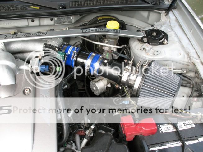
sparks, that all black intake is FIRE! was it easy to move the battery over?
sparks, that all black intake is FIRE! was it easy to move the battery over?
Last edited by shdwonthsun; Jan 4, 2011 at 12:40 PM.
DO NOT DO BUSINESS WITH THIS MEMBER - OWES PEOPLE MONEY
iTrader: (7)
Joined: Jan 2008
Posts: 3,468
From: Greensboro, NC
edit: the reason I did that is because I still have my CAI hole opened up there, and fresh/cool air comes in through the lower grill opening
 .
.
Last edited by sparks03max; Jan 4, 2011 at 01:42 PM.
DO NOT DO BUSINESS WITH THIS MEMBER - OWES PEOPLE MONEY
iTrader: (7)
Joined: Jan 2008
Posts: 3,468
From: Greensboro, NC
I was under the impression that the spot where the little filter is has positive pressure, which will not cause a vacuum leak. Putting a straight pipe on behind the maf, or hooking the MAF to the TB will not cause a vacuum leak. You will blow oil out where you have the little filter.
that doesn;t make sense. The exit from the cover goes to the pipe in the intake just in front of the TB. In front of the TB is a vacuum, air is being sucked into the TB. Air cannot be sucked into the valve cover and the intake at the same time when they are connected together. The exit from the valve cover probably has light positive pressure, and the intake side acts as a vacuum

The flow follows the green arrows, you are saying it follows the white arrows...
The flow follows the green arrows, you are saying it follows the white arrows...
DO NOT DO BUSINESS WITH THIS MEMBER - OWES PEOPLE MONEY
iTrader: (7)
Joined: Jan 2008
Posts: 3,468
From: Greensboro, NC
that doesn;t make sense. The exit from the cover goes to the pipe in the intake just in front of the TB. In front of the TB is a vacuum, air is being sucked into the TB. Air cannot be sucked into the valve cover and the intake at the same time when they are connected together. The exit from the valve cover probably has light positive pressure, and the intake side acts as a vacuum
The flow follows the green arrows, you are saying it follows the white arrows...
The flow follows the green arrows, you are saying it follows the white arrows...
shdwonthsun knows what's up.
Last edited by sparks03max; Jan 4, 2011 at 06:39 PM.
nicely said, and completely correct. it just seems like all that smoothing of the air is in vain when it slams to a halt at the intake valves. in (slow air moving) car engines, its not how fast, its how much. it honestly doesn't care. and without a compressor the motor is gonna have no problem sucking in the tiny amount of air it needs, whether its smoothed for the first few inches (as the intake tract tears it up immediately) or all jumbled for those first few inches. its just seems futile to me.
make one of these to go after the intake valve, ill buy 6
cmax, i like that hybrid. isn't there a way we can delete that last resonator?
make one of these to go after the intake valve, ill buy 6
cmax, i like that hybrid. isn't there a way we can delete that last resonator?
Last edited by CMax03; Jan 4, 2011 at 06:59 PM.
DO NOT DO BUSINESS WITH THIS MEMBER - OWES PEOPLE MONEY
iTrader: (7)
Joined: Jan 2008
Posts: 3,468
From: Greensboro, NC
It doesn't just slam into the intake valve will it shuts.....Initially it flows thru the intake right out the exhaust during valve overlap (headers and a performance exhaust aid in the scavange effect at this point)the faster the exhaust leaves the faster the intake charge will be enter, due to the momentum and scavenging down stream! Decreasing the restriction on the intake side with aid of a larger free flowing air fliter and Velocity stack just makes things a lot easier in building up the velocity and fluid momentum! Oh yeah I don't want to hear too much growling and the throttle seems more linear with the Helmhotz resonator, so It'll stay for the time being until I make My own midpipe or buy one from Knight


DO NOT DO BUSINESS WITH THIS MEMBER - OWES PEOPLE MONEY
iTrader: (7)
Joined: Jan 2008
Posts: 3,468
From: Greensboro, NC
but the pcv valve is on the other valve cover at the back. Where you put your dinky filter is just an opening. There is no pcv valve.

pcv is circled, the brown line reps the hose from rocker to rocker, the two arrows vent to the intake manifold and is under vacuum.... your dinky air filter is nowhere near the pcv
pcv is circled, the brown line reps the hose from rocker to rocker, the two arrows vent to the intake manifold and is under vacuum.... your dinky air filter is nowhere near the pcv
MY fun factor is excellent Part throttle response unless you drive around a HighBanked Oval @ WOT going to work or whatever! I live in the real world and I'm not saying I don't like WOT...That I do!!!!!! but rolling into the throttle and having the engine respond with excellent driveability is something I love....I Hate sluggish, non-crisp engine response!!!!
Last edited by CMax03; Jan 5, 2011 at 09:51 PM.
DO NOT DO BUSINESS WITH THIS MEMBER - OWES PEOPLE MONEY
iTrader: (7)
Joined: Jan 2008
Posts: 3,468
From: Greensboro, NC
but the pcv valve is on the other valve cover at the back. Where you put your dinky filter is just an opening. There is no pcv valve.
pcv is circled, the brown line reps the hose from rocker to rocker, the two arrows vent to the intake manifold and is under vacuum.... your dinky air filter is nowhere near the pcv
pcv is circled, the brown line reps the hose from rocker to rocker, the two arrows vent to the intake manifold and is under vacuum.... your dinky air filter is nowhere near the pcv
DO NOT DO BUSINESS WITH THIS MEMBER - OWES PEOPLE MONEY
iTrader: (7)
Joined: Jan 2008
Posts: 3,468
From: Greensboro, NC
MY fun factor is excellent Part throttle response unless you drive around a HighBanked Oval @ WOT going to work or whatever! I live in the real world and I not saying I don't like WOT...That I do!!!!!! but rolling into the throttle and having the engine respond with excellent driveability is something I love....I Hate sluggish, non-crisp engine response!!!!
edit: oh and sprint booster would not only remove any lag in your response, but would also make 20% throttle feel more like 30% throttle and 70% more like 100%, meaning MORE POWA!!!!
Last edited by sparks03max; Jan 4, 2011 at 08:11 PM.


this whole thread is so informative, also very confusing. Seems like everyone is talking about different ways this vacuum thing works. I'll just stick to my stolen Altima Nismo intake that was in my Sentra b4 i wrecked her.