
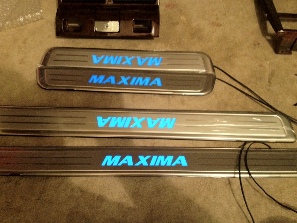
hey guys I just bought a set of these:
http://www.paradox-systems.com/produ...products_id=65
and I did find some instructions by searching to put them together here:
http://www.lehrner.com/david/indiglo/indiglo.html
but that seems to be an older set? The set I received today has both front and rear light-up sills not just the front. So I have the instructions that came with it here:
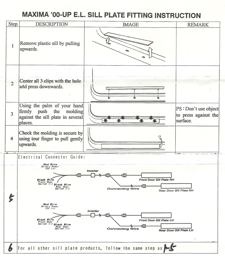
and it seems easy enough... but since the instructions are different in the image and the link above, and there's an extra ground... I was just wondering if anyone experienced in this could help me out with EXACTLY which wires I should be tapping into here. I know how to run them and do the install, just need to know which wires. If you need pictures of the sills with the wiring I can post that up.
I also want this to be kind of a guide for anyone else that buys these, since when I was searching I was sifting through hours of threads from 2002-2005 that don't 100% apply to today.
I still want to hook them up to the door light wires as described in the above link if thats possible. If I have to go in behind the fuse box please give me details as I've never gone back there before.
http://www.paradox-systems.com/produ...products_id=65
and I did find some instructions by searching to put them together here:
http://www.lehrner.com/david/indiglo/indiglo.html
but that seems to be an older set? The set I received today has both front and rear light-up sills not just the front. So I have the instructions that came with it here:
and it seems easy enough... but since the instructions are different in the image and the link above, and there's an extra ground... I was just wondering if anyone experienced in this could help me out with EXACTLY which wires I should be tapping into here. I know how to run them and do the install, just need to know which wires. If you need pictures of the sills with the wiring I can post that up.
I also want this to be kind of a guide for anyone else that buys these, since when I was searching I was sifting through hours of threads from 2002-2005 that don't 100% apply to today.
I still want to hook them up to the door light wires as described in the above link if thats possible. If I have to go in behind the fuse box please give me details as I've never gone back there before.

Member
When you say extra ground do you mean an extra ground in the door wiring or on the sill you bought? Either way you really just need battery power and the wires for the door switches. If you own a multimeter this should be very easy to accomplish, just test for bat voltage, and then test for voltage with door open/closed to find the right wires.
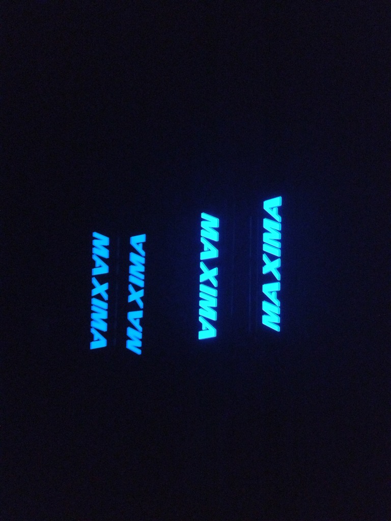
The sills are nice looking but that blue is ugly. I may buy a pair and take 'em apart and swap it for a white LED or something a little less turquoise.
The sills are nice looking but that blue is ugly. I may buy a pair and take 'em apart and swap it for a white LED or something a little less turquoise.

Senior Member
There is certainly an awful lot of missing information. The Paradox web site is useless for information. The photo instructions on lehrner.com assume you have done this job a 1000 times and you aren't quite descriptive enough, either.
a) To start with, does the product you have use the illumination control shown on lehrner.com?
b) What is the inverter shown in step 5 of the instructions? The illumination control?
c) This extra ground wire you refer to - is it shown in the instructions?
d) The instructions you posted - is that the complete instructions?
The lerner.com photo instructions show the guy tapping into the step light in the door. The instructions you posted, step 5, do not imply that you do that. In fact, you can't on the rear doors as there are no lights in them, at least on the 5.0.
The step 5 instructions label the black wires as connecting to the door switches. This is straight forward for the rear doors, but not for the front doors.
The 12 volt hook-up seems straight forward, but you mention connecting on the back of the fuse panel. Are the directions telling you to do that or is that your preference?
I would need a lot more info to do this. If you have posted all the info you have, I definitely understand your problem.
Quote:
a) To start with, does the product you have use the illumination control shown on lehrner.com?
b) What is the inverter shown in step 5 of the instructions? The illumination control?
c) This extra ground wire you refer to - is it shown in the instructions?
d) The instructions you posted - is that the complete instructions?
The lerner.com photo instructions show the guy tapping into the step light in the door. The instructions you posted, step 5, do not imply that you do that. In fact, you can't on the rear doors as there are no lights in them, at least on the 5.0.
The step 5 instructions label the black wires as connecting to the door switches. This is straight forward for the rear doors, but not for the front doors.
The 12 volt hook-up seems straight forward, but you mention connecting on the back of the fuse panel. Are the directions telling you to do that or is that your preference?
I would need a lot more info to do this. If you have posted all the info you have, I definitely understand your problem.
That's all the info I have. I could be a little more descriptive about it though so I apologize. Originally Posted by DennisMik
a) To start with, does the product you have use the illumination control shown on lehrner.com?
b) What is the inverter shown in step 5 of the instructions? The illumination control?
c) This extra ground wire you refer to - is it shown in the instructions?
d) The instructions you posted - is that the complete instructions?
The lerner.com photo instructions show the guy tapping into the step light in the door. The instructions you posted, step 5, do not imply that you do that. In fact, you can't on the rear doors as there are no lights in them, at least on the 5.0.
The step 5 instructions label the black wires as connecting to the door switches. This is straight forward for the rear doors, but not for the front doors.
The 12 volt hook-up seems straight forward, but you mention connecting on the back of the fuse panel. Are the directions telling you to do that or is that your preference?
I would need a lot more info to do this. If you have posted all the info you have, I definitely understand your problem.
A) there is no control pod, only what you see in the diagram.
B) the inverter is just a power inverter. No controls or anything on it. I would assume maybe to regulate the power like a fuse.
C) the extra ground wire is on the wiring diagram. On Lerner.com they talk about hooking up to 1 + and 1 - on the wires leading from the front door lights, nothing in the rear. Being that this has the rear sill illuminated as well it has 1+, and 2-, 1 for the front and 1 for the rear. Both wires would be near the front of the car and the rear sill hooks into the power chain where it meets the front sill, then it continues up. Theoretically I guess I could hook both grounds up to the same wire leading from the door lights where Lerner.com shows you would hook the 1 ground into. I don't know if that would cause a problem. I'll have to post actual pictures of what the signal path would be so you can see.
D) yes that's the complete instructions
I would prefer not going behind the fuse box. The instructions only say to hook up to a 12v positive. Doesn't say where.
Quote:
The sills are nice looking but that blue is ugly. I may buy a pair and take 'em apart and swap it for a white LED or something a little less turquoise.
Lol yea it kind of is. I was thinking the same but LEDs come out ****ty because its not uniform. Gotta get an EL strip. I'll hook em up and see how satisfied I am first. It's supposed to be a bluer blue when theyre lit up.Originally Posted by andrewmac
When you say extra ground do you mean an extra ground in the door wiring or on the sill you bought? Either way you really just need battery power and the wires for the door switches. If you own a multimeter this should be very easy to accomplish, just test for bat voltage, and then test for voltage with door open/closed to find the right wires.The sills are nice looking but that blue is ugly. I may buy a pair and take 'em apart and swap it for a white LED or something a little less turquoise.
Unfortunately I don't have a multimeter, Just a tester.


All you need to do for the sills is positive goes to a +12v /negative door pinswitch trigger
Sent from my ****
Sent from my ****
Quote:
Sent from my ****
The black negative wire reaches perfectly too to the door switches. I just mounted the drivers side sills and some of the wiring and I see how it works now. So I'll run the negative to each door switch then. Can I use the + wire from the door lights as they show on lehrner.com or is there a better source for me to tap into? If so what color wire/where can I find it? (Sorry no multimeter)Originally Posted by cjandura
All you need to do for the sills is positive goes to a +12v /negative door pinswitch triggerSent from my ****
I like that color too actually. It'll work with the blue LEDs I have in the doors and dome.
Senior Member
Do not tap the power from the door lights. I am not sure if it is hot all the time, such as when the door is closed. But more importantly is that the door light, both ground and 12 volt wires, is wired to the driver's door power window switch. That window switch is a microprocessor controlled device and may not be able to handle the extra current demand.
For what it's worth, an inverter changes DC power into AC power. The letters in the sill plates are like flourescent lights, which must have AC power in order to light up.
For what it's worth, an inverter changes DC power into AC power. The letters in the sill plates are like flourescent lights, which must have AC power in order to light up.
Damn... They should tell you which wire to tap into for this lol. Everything else is easy enough. So does anyone know what positive wire I should tap into? For both driver side and passenger?
Quote:
Thanks, anything on passenger side? Or should I get another wire and extend it to the driver seat also?Originally Posted by DennisMik
You could tap into the power seat wiring. Yellow wire.
I think the wiring is different on the 2k2. Didn't see a yellow wire under the seat. Poked around at a few connections with the test light and didn't get anything either. I got the - wires into the door switches. The front one is retarded, I had to use the green wire instead of the black. When I tapped into the black and pressed the switch it wouldn't register that the door was closed. Thought I broke something at first lol then I realized it was just the wrong wire. I did jam the + wire into the dome light fuse just to check Out how it looks and it definitely looks sexy. i like the color just fine. I'll have to play with it more in the am.
You can get the el light strip online and change the color if you want just buy the 2" wide and be careful taking the door sills apart
Sent from my ****
Sent from my ****
Still not sure which wire to tap into. What if I get a fuse tap like this?
http://www.autozone.com/autozone/acc...uestid=3768577
Or something similar? Can I just wire both sides into the dome light fuse (10a) this way? Sorry guys, I know how to solder and all that, just a little inexperienced at automotive wiring.
http://www.autozone.com/autozone/acc...uestid=3768577
Or something similar? Can I just wire both sides into the dome light fuse (10a) this way? Sorry guys, I know how to solder and all that, just a little inexperienced at automotive wiring.
Just use the blue or red wiretaps dont tap the dome light grab the +12 from the power seat harness and the -12 from the door pin
Sent from my ****
Sent from my ****
Senior Member
Quote:
Well, according to both versions of the FSM for the 2002 Maxima, the wire is yellow. Both versions of the 2000 manual, the 2001 manual and the 2003 manual also say yellow. I don't know what to say. I do know that there are errors in the manual, just no experience with power seat wiring.Originally Posted by nycibbyryder
I think the wiring is different on the 2k2. Didn't see a yellow wire under the seat. Poked around at a few connections with the test light and didn't get anything either.
I assumed you had power seats on both sides, I guess I assumed wrong. Even if you don't, you should have the power seat wire harness connector hiding somewhere under the seat. I figured the power seat wire would be close and handy so I suggested that.
You can connect the door sill red wire to any 12 volt source so long as it is hot when the ignition switch is off. You can hook both wires to the same spot if you want to. All you have to do is check that the circuit you hook into can handle the extra amps the door sills will require.
That tap that you saw at autozone should work. I've never used one like that, so I can't say 100% positively.
Yea sorry thanks for the suggestion I do appreciate the help tons. I checked with the test light and there's constant power to the dome light fuse whether the doors are open or closed. Same with 3 others the trunk, one labeled 'electrical parts', and something else I dont remember though. I like the power seat idea though. Constant power that's really never being used so it'd be perfect, but yea only on drivers side, passengers is manual. Maybe I have to look harder or further under the seat.
I never saw anything like that either, I was looking around on YouTube and a couple guys used it to hardwire GPS units and radar detectors so it seemed like a good idea. Guess ill look further under the seat tomorrow then. Thanks again for the help also
I never saw anything like that either, I was looking around on YouTube and a couple guys used it to hardwire GPS units and radar detectors so it seemed like a good idea. Guess ill look further under the seat tomorrow then. Thanks again for the help also

Newbie - Just Registered
I've got a 2001 Nissan Maxima SE and just purchased the same set of illuminated door sills. This forum is the only place that I could find any information on them in terms of wiring and what not. As I was hooking them up yesterday I found that the diagram above was very helpful but I still have a few loose ends to tie up. I was curious if it would make sense to tie the black (door switch wires) into the fuse that controls the door lights and then just tie the red (power wires) directly to the battery wire. Or maybe it would make sense to tie the red wires to the fuse and black to somewhere else?
The person I bought them from said that he hooked up the red wire to the SECU wire in the kick panel area and then ran the black to the chassis for a ground, I assume. Either way I guess I'll just play around with it until I find something that works.
The person I bought them from said that he hooked up the red wire to the SECU wire in the kick panel area and then ran the black to the chassis for a ground, I assume. Either way I guess I'll just play around with it until I find something that works.