

3rd gen VQ35DE Full ECU Swap Progress Thread

Thread Starter
NWP Engineering.com
iTrader: (128)
Joined: Jul 2001
Posts: 14,065
From: Walstonburg, NC
Just a few minutes ago, I installed the axle. The ABS ring didn't want to fit in the hub though. But I grinded about 15 thou out of the hub and it now fits and the wheel spins freely.

Same here! I thought this axle situation was going to set me back by more than a week. But, I was happy when I measured the VQ axle overall length.
Just a few minutes ago, I installed the axle. The ABS ring didn't want to fit in the hub though. But I grinded about 15 thou out of the hub and it now fits and the wheel spins freely.
Just a few minutes ago, I installed the axle. The ABS ring didn't want to fit in the hub though. But I grinded about 15 thou out of the hub and it now fits and the wheel spins freely.
so the motor is in
soon to be running?


Thread Starter
NWP Engineering.com
iTrader: (128)
Joined: Jul 2001
Posts: 14,065
From: Walstonburg, NC
Yes, motor is in as shown in the pic. 
My goal is to try to fire it up by Monday if possible. We'll see how things go. I'm sure there will be more obstacles.
Thanks.
The brackets aren't a plug and play type of thing. One of them had to be modified. I will post pictures soon.
My goal is to try to fire it up by Monday if possible. We'll see how things go. I'm sure there will be more obstacles.
Thanks.
The brackets aren't a plug and play type of thing. One of them had to be modified. I will post pictures soon.
Thread Starter
NWP Engineering.com
iTrader: (128)
Joined: Jul 2001
Posts: 14,065
From: Walstonburg, NC
I've been VERY busy with this project the past couple months. I've been so busy that I haven't had time to post pictures as I did the work. Let me catch up. 56K warning!
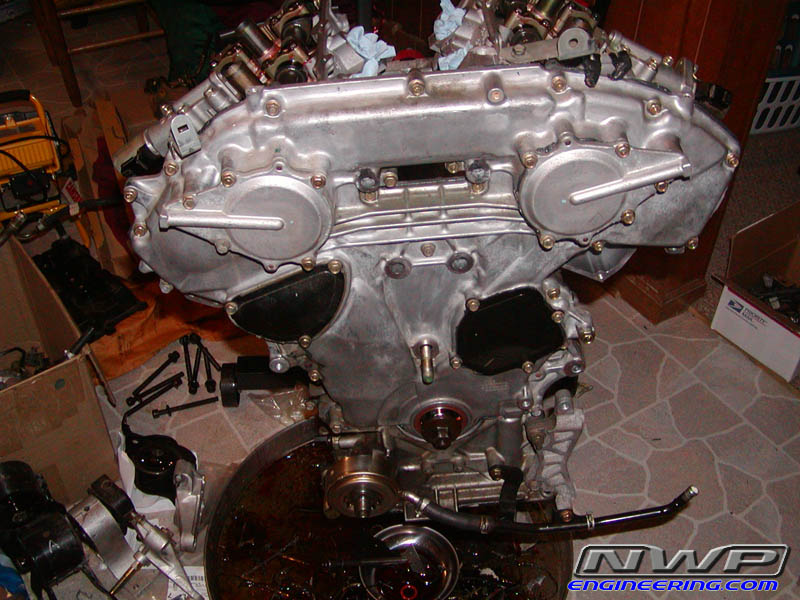
Heads installed:

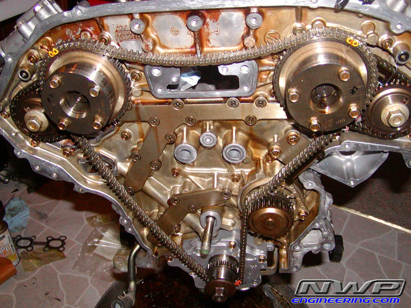
Rear Timing Cover installed:

Timing Chain put on:
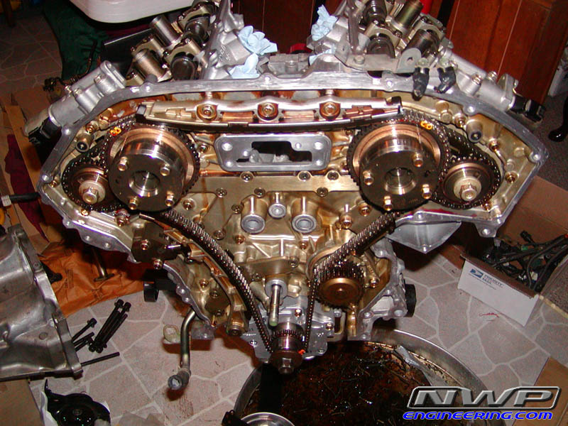
Tensioners put on:

Heads installed:
Rear Timing Cover installed:
Timing Chain put on:
Tensioners put on:
Thread Starter
NWP Engineering.com
iTrader: (128)
Joined: Jul 2001
Posts: 14,065
From: Walstonburg, NC
Front Timing Cover installed:

Oil pan is next:
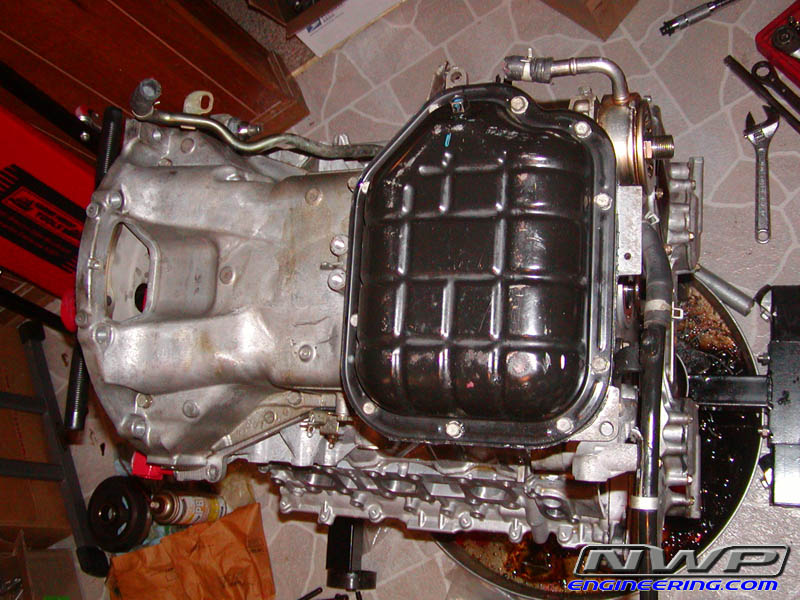
Intake Manifolds next:
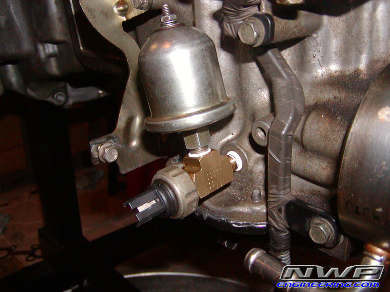
Here was my oil pressure switch and OP gauge sending unit. But during the install, I found out that it's in the way of the passenger side axle. So, just yesterday, I removed the dummy light switch and screwed the sending unit in by itself.
Oil pan is next:
Intake Manifolds next:
Here was my oil pressure switch and OP gauge sending unit. But during the install, I found out that it's in the way of the passenger side axle. So, just yesterday, I removed the dummy light switch and screwed the sending unit in by itself.
Thread Starter
NWP Engineering.com
iTrader: (128)
Joined: Jul 2001
Posts: 14,065
From: Walstonburg, NC
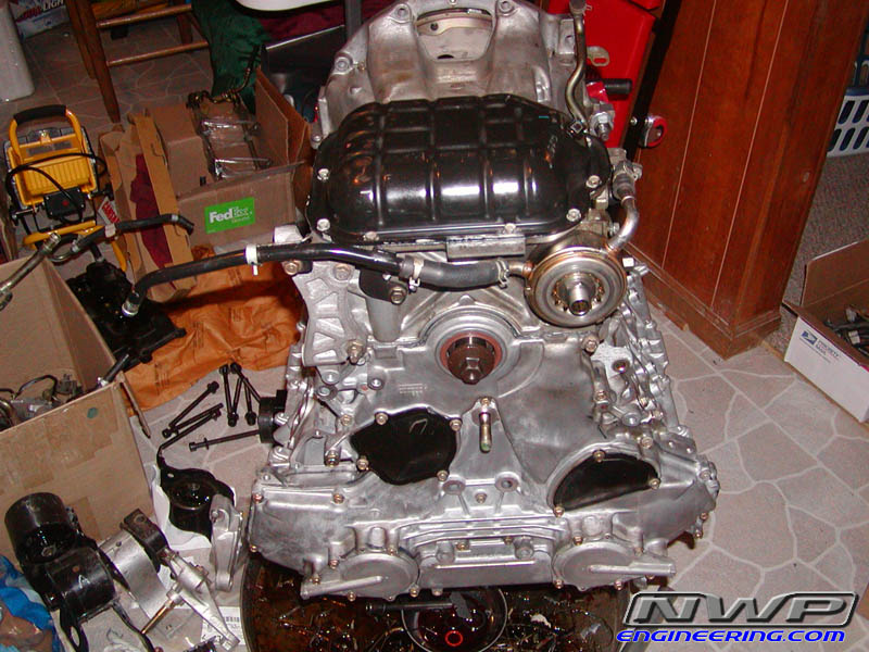
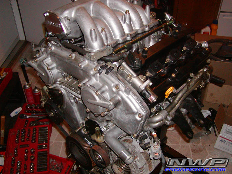
Timing Cover and Pan all installed:
Engine is all ready for the swap!
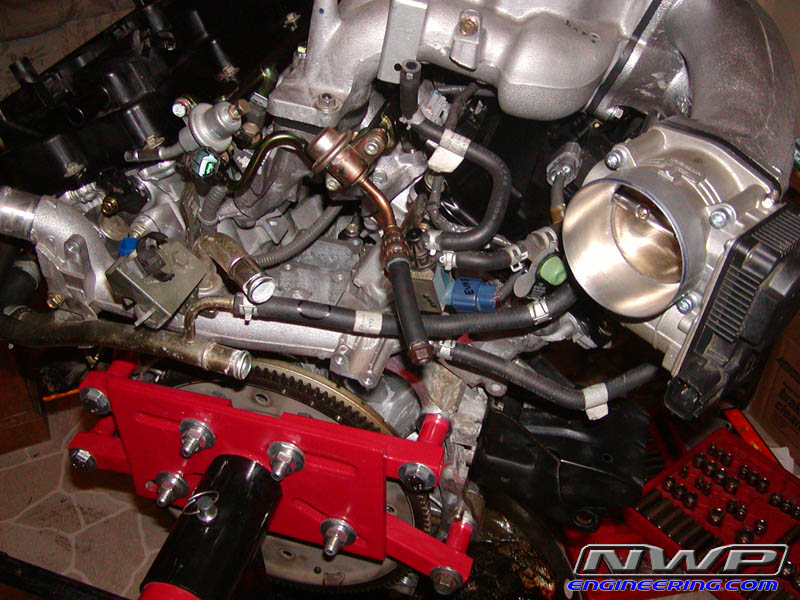
I know I have the throttle body upside down. I found that out later when I was plugging in my EC harness. I fixed it.

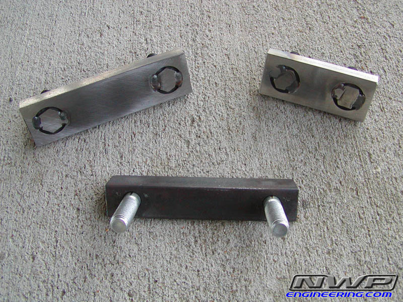
Here are the brackets I had made by one of my local machinists. My 'Plan A' was to use the short one for the rear and the angle iron one for the front. The angle iron was suppose to sit above the lip on the front of the car and provide extra metal to weld onto for reinforcement. But that didn't work. More details are given later during the install process.
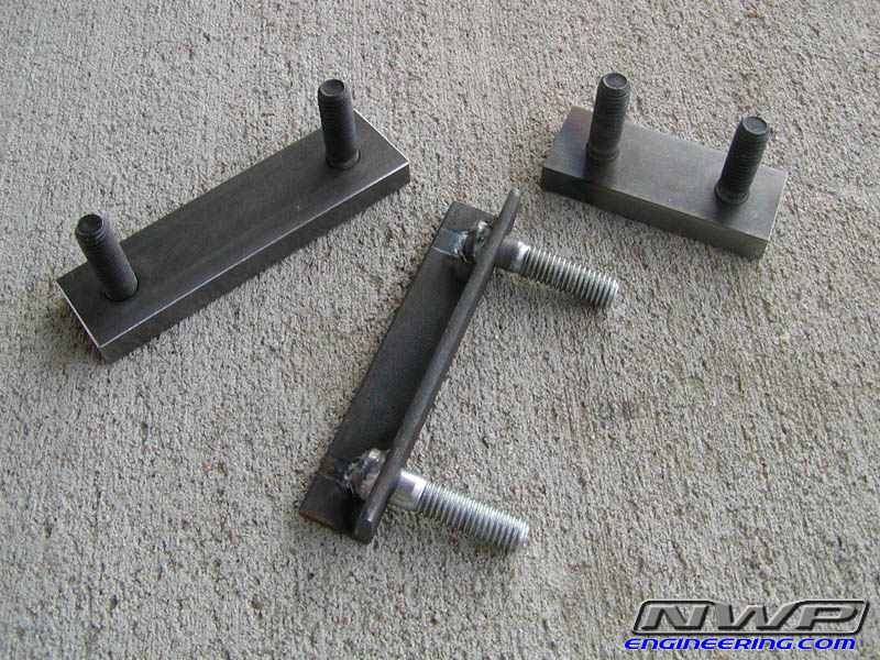
Another shot. Beautiful work, huh?
Engine is all ready for the swap!
I know I have the throttle body upside down. I found that out later when I was plugging in my EC harness. I fixed it.
Here are the brackets I had made by one of my local machinists. My 'Plan A' was to use the short one for the rear and the angle iron one for the front. The angle iron was suppose to sit above the lip on the front of the car and provide extra metal to weld onto for reinforcement. But that didn't work. More details are given later during the install process.
Another shot. Beautiful work, huh?
Thread Starter
NWP Engineering.com
iTrader: (128)
Joined: Jul 2001
Posts: 14,065
From: Walstonburg, NC
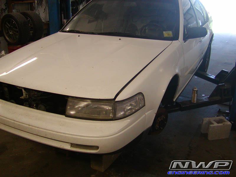
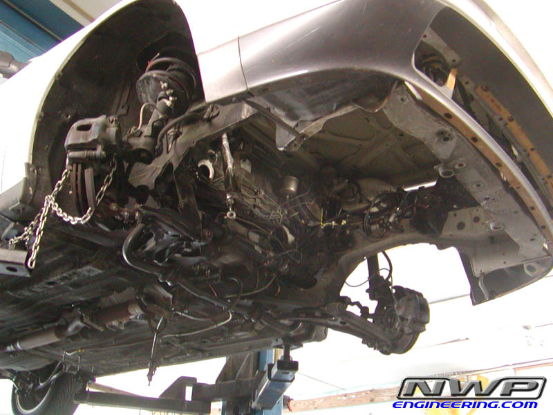
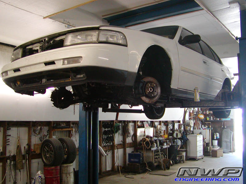
Here's the car on the lift. The entire engine swap took a day and a half to complete. I was hoping to have the entire job done in less than 8 hours though. But we ran into little issues with axle fitment, crossmember bracket fitment, and the front engine mount.
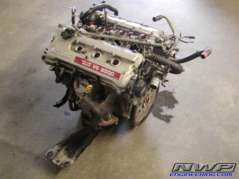
The old VE engine and transmission dropped from underneath:
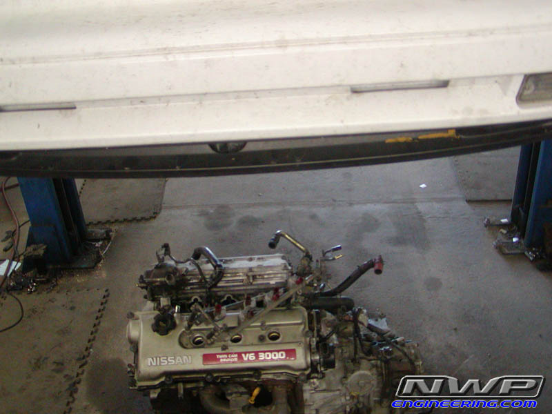
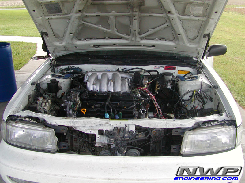
No engine in bay:
Another shot of old engine:
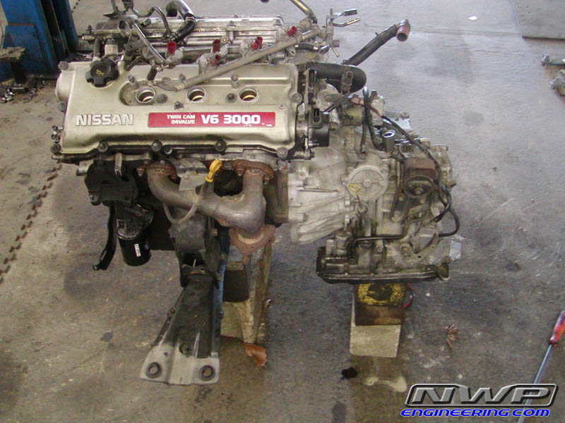
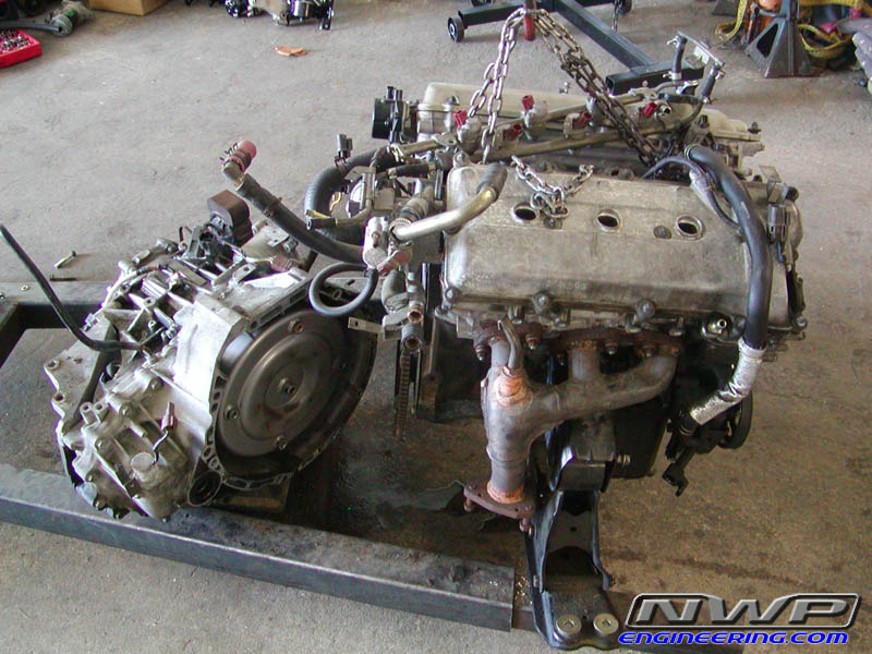
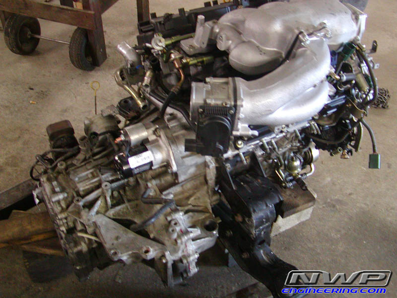
Separated the transmission from the engine so I could use it on the VQ35DE.
The old VE engine and transmission dropped from underneath:
No engine in bay:
Another shot of old engine:
Separated the transmission from the engine so I could use it on the VQ35DE.
Thread Starter
NWP Engineering.com
iTrader: (128)
Joined: Jul 2001
Posts: 14,065
From: Walstonburg, NC
Bye bye VE! It's been fun, but time to upgrade!
Had to swap torque converter housings to allow the RE4F04V to bolt up to the VQ block. I used a 4th gen torque converter housing from an RE4F04A trans. Worked exactly as planned!
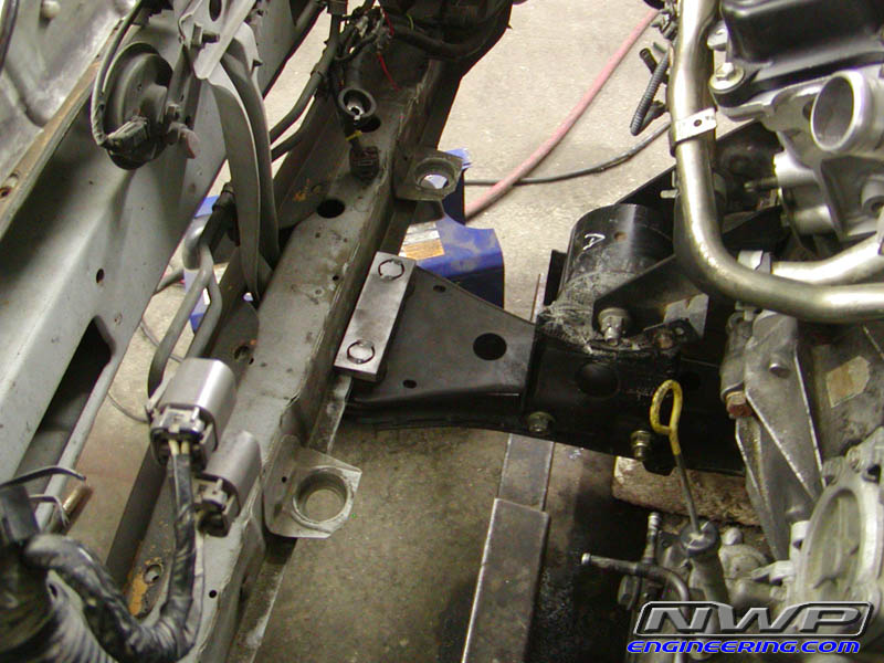
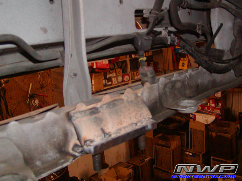
Here's some shots of the crossmember brackets going in. As you can see, I couldn't use the angle iron 'Plan A' bracket. I left the tranny in the stock location using the stock mounts. So where ever the engine ended up, it is what it is. The crossmember was about 1/2" towards the rear of the car, more than I expected. So there was no way to use the angle iron bracket for the front. The "Plan B" bracket for the front was used. I was going to install this up underneath the front beam of the car. The angle iron bracket was going to go above the lip to help raise the crossmember up. I didn't want the crossmember hanging down any further than what it was to begin with. It was way too low, especially with 22" slicks mounted. So instead of putting the Plan B bracket underneath the front beam, we put it on top of the lip and it fit up tight in that corner as shown. But ALL the weight is resting on that lip, which is very weak. You can bend it with pliers pretty easily.
Welded:

So a diagonal reinforcing plate was installed giving it the same strength as what the angle iron bracket would have given. The radiator does touch, but it won't be a problem.
Had to swap torque converter housings to allow the RE4F04V to bolt up to the VQ block. I used a 4th gen torque converter housing from an RE4F04A trans. Worked exactly as planned!
Here's some shots of the crossmember brackets going in. As you can see, I couldn't use the angle iron 'Plan A' bracket. I left the tranny in the stock location using the stock mounts. So where ever the engine ended up, it is what it is. The crossmember was about 1/2" towards the rear of the car, more than I expected. So there was no way to use the angle iron bracket for the front. The "Plan B" bracket for the front was used. I was going to install this up underneath the front beam of the car. The angle iron bracket was going to go above the lip to help raise the crossmember up. I didn't want the crossmember hanging down any further than what it was to begin with. It was way too low, especially with 22" slicks mounted. So instead of putting the Plan B bracket underneath the front beam, we put it on top of the lip and it fit up tight in that corner as shown. But ALL the weight is resting on that lip, which is very weak. You can bend it with pliers pretty easily.
Welded:
So a diagonal reinforcing plate was installed giving it the same strength as what the angle iron bracket would have given. The radiator does touch, but it won't be a problem.
Thread Starter
NWP Engineering.com
iTrader: (128)
Joined: Jul 2001
Posts: 14,065
From: Walstonburg, NC
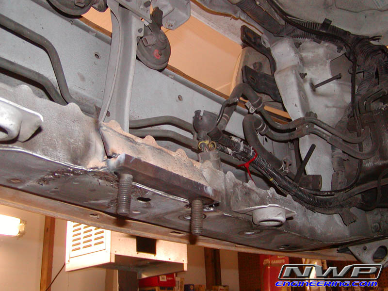
The rear bracket was installed as planned:
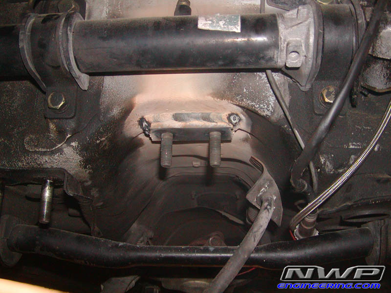
As previously mentioned, the front engine mount was a problem. What mmg23max did on his VQ35 swap was cut the motor mount housing out of the engine bay of a 4th gen. Then he welded that to the 3rd gen after he bent all his ABS line out of the way. I don't have easy access to a 4th gen, so I decided just to make a solid mount using the two M6 holes already in the 3rd gen body. I didn't have to move the ABS lines. It's a pretty weak mount especially considering the base is held in by only two M6 bolts. But we'll see how it holds. The two main mounts are poly filled and should be pretty sturdy.

Another shot of car on lift:
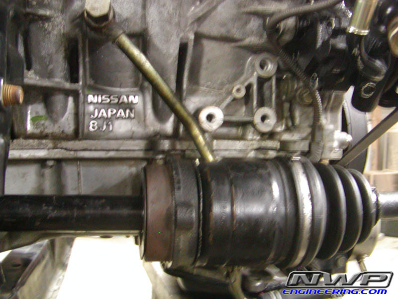
In this pic, you'll see a VE axle axle with the VQ35 block. The support bracket location on the VE axle is 3" closer to the tranny than the one for the VQ. I first thought to fab up a custom support bracket and still use my stock VE axle. But I quickly found out that the headers wouldn't work without major reconstruction! So to get my car out of the shop, I just postponed that problem for another day. I later found out that the 4th gen axle works in the 3rd gen. The ABS ring is a tad different and won't line up perfectly with the ABS sensor, but it may still pick up a signal. Also, as mentioned in my post last night, the ABS ring is a tad too large for the 3rd gen hub. So I grinded a little bit on the hub and now it fits.
Well that's all my swap pics!


Thread Starter
NWP Engineering.com
iTrader: (128)
Joined: Jul 2001
Posts: 14,065
From: Walstonburg, NC
Probably around $150-200 for those two brackets. They aren't cheap. And as you can see, they are flawless. But, you'll have to fab up that diagonal plate yourself though since the angle iron bracket didn't work out.

Senior Member
Joined: Nov 2006
Posts: 539
sweet, i will let you know when/if you can send a set.
Thread Starter
NWP Engineering.com
iTrader: (128)
Joined: Jul 2001
Posts: 14,065
From: Walstonburg, NC
It should. It's the same as the 4th gen trannies and they hold up ok. But, my tranny is original at 203K. So who knows how long it'll last.
No problem.
Thread Starter
NWP Engineering.com
iTrader: (128)
Joined: Jul 2001
Posts: 14,065
From: Walstonburg, NC
I just finished wiring everything up and I plugged in my battery for the first time. Everything turns on and the fuel pump is building pressure like it should.
But, what is the security light suppose to do when you first turn the ignition switch to ON? Mine doesn't do anything. It just stays off.
But when the key is OFF or ACC, the light blinks. Is this all normal?
But, what is the security light suppose to do when you first turn the ignition switch to ON? Mine doesn't do anything. It just stays off.
But when the key is OFF or ACC, the light blinks. Is this all normal?
If the security light stays on while the key is ON or while cranking, then the ECU/NATS isn't recognizing the key.
You know damn well org hell will be brought upon you if you don't record the first startup and put it online

Thread Starter
NWP Engineering.com
iTrader: (128)
Joined: Jul 2001
Posts: 14,065
From: Walstonburg, NC
So, is that the normal thing to do? Take a video of initial startup? The first startup can be very nerve racking. I was nervous giving juice to my ECU for the first time.
I may just put fluids in the engine, tranny, and radiator and fire this thing up tonight. I still have to install the LH header and o2 sensor.
But all the codes I'm getting are expected things like EVAP and VIAS. So that is good.
Ok thanks. So the security light isn't suppose to come on for a few seconds and then go out when the ignition is ON? My just stays out the entire time.
So, is that the normal thing to do? Take a video of initial startup? The first startup can be very nerve racking. I was nervous giving juice to my ECU for the first time.
I may just put fluids in the engine, tranny, and radiator and fire this thing up tonight. I still have to install the LH header and o2 sensor.
But all the codes I'm getting are expected things like EVAP and VIAS. So that is good.
After this long of a project, I think an initial startup vid would be a good thing to make. And of course, we all want to see it.
Thread Starter
NWP Engineering.com
iTrader: (128)
Joined: Jul 2001
Posts: 14,065
From: Walstonburg, NC
My initial startup will consist of a camshaft break in procedure. So as soon as I crank it, if I feel everything is ok, I will let it run at 2K rpm for a while. So I have to get all the fluids in the car and make sure the cooling fans kick on like they should. All this will be open headers as well since I have to have my Ypipe custom made.
Yeah, thanks. I was just making sure.
My initial startup will consist of a camshaft break in procedure. So as soon as I crank it, if I feel everything is ok, I will let it run at 2K rpm for a while. So I have to get all the fluids in the car and make sure the cooling fans kick on like they should. All this will be open headers as well since I have to have my Ypipe custom made.
My initial startup will consist of a camshaft break in procedure. So as soon as I crank it, if I feel everything is ok, I will let it run at 2K rpm for a while. So I have to get all the fluids in the car and make sure the cooling fans kick on like they should. All this will be open headers as well since I have to have my Ypipe custom made.

i like the way you set about doing all the wiring ahead of time, that way when you got the engine in it was *almost* just like putting in the engine that belonged in the car.
Yeah, thanks. I was just making sure.
My initial startup will consist of a camshaft break in procedure. So as soon as I crank it, if I feel everything is ok, I will let it run at 2K rpm for a while. So I have to get all the fluids in the car and make sure the cooling fans kick on like they should. All this will be open headers as well since I have to have my Ypipe custom made.
My initial startup will consist of a camshaft break in procedure. So as soon as I crank it, if I feel everything is ok, I will let it run at 2K rpm for a while. So I have to get all the fluids in the car and make sure the cooling fans kick on like they should. All this will be open headers as well since I have to have my Ypipe custom made.

.
Thread Starter
NWP Engineering.com
iTrader: (128)
Joined: Jul 2001
Posts: 14,065
From: Walstonburg, NC
Today, I finished up the DPST ECCS relay. I just pulled the pins out of the stock SPST ECCS relay and plugged them in the DPST and ran a separate 15A fuse to the battery as the 02 Maxima FSM shows. Then I found an empty slot on the passenger side engine bay relay box for my Throttle Motor Control Relay to go. I did the same thing and pulled some pins out of spare relay sockets that I had and soldered everything in. I had to pulled several feet of wire to the other side of the engine bay where the battery is to give it power (15A fused). I undid the wiring harness underneath the front engine bay rail and tucked my wiring carefully away so you can't see it. The engine really does look like it came that way from the factory! Well, except for my ugly solid front engine mount.
Haha! I am not getting my hopes up though. Cause I know I will run into more obstacles. That's what I'm telling myself. Take it one day at a time.
I finished all the wiring today and gave power to the ECU. Fuel pressure seems to be fine. The only codes I'm getting are ones I expected, which is GREAT NEWS. I am only getting 85% throttle though and I can't figure out why. The APP sensor is in spec according to the voltage specifications in the FSM at the two ECU terminals. I pulled the ASCD brake switch and that didn't help. If anybody has any ideas, please let me know.
I bolted up the new steering wheel and plugged everything in and everything works on the cluster! Turn signals, horn, etc. The high beam light doesn't work, so I'll fix that some other time. And the gear selection works somewhat decently. If you have the OD off, it will show 3rd gear no matter which gear you're actually in. But, if the OD is on, it will show the right gear.
Tomorrow, I plan to attempt to fire this engine up. Coolant, Oil, and tranny fluid and I should be set. Oh yeah, I have to finish wiring in my manual high speed cooling fans switch first to make sure my fans work like they should before cranking this engine.
Exciting times! I really appreciate everyone's interest!
Do all of the learning procedures here:
http://www.technosquareinc.com/350reset.htm
Same thing as the Z33.
As for the IAVL, you shouldn't need to start it up at all. They're all worth a shot, anyway.
http://www.technosquareinc.com/350reset.htm
Same thing as the Z33.
As for the IAVL, you shouldn't need to start it up at all. They're all worth a shot, anyway.
Thread Starter
NWP Engineering.com
iTrader: (128)
Joined: Jul 2001
Posts: 14,065
From: Walstonburg, NC
Do all of the learning procedures here:
http://www.technosquareinc.com/350reset.htm
Same thing as the Z33.
As for the IAVL, you shouldn't need to start it up at all. They're all worth a shot, anyway.
http://www.technosquareinc.com/350reset.htm
Same thing as the Z33.
As for the IAVL, you shouldn't need to start it up at all. They're all worth a shot, anyway.
I know Jime was having problems with not reaching 100% WOT and it was due to the brake switch. When the brakes are engaged, it limits throttle position. This effects you being able to stall it up at the line if needed. For the VE, I've found that I get better 60 foots by not stalling it up and just shocking the converter from near idle. But that could change drastically with this new engine.
Oh, and I didn't reset the ECU using that procedure. All I've done is clear the codes a few times.
Thread Starter
NWP Engineering.com
iTrader: (128)
Joined: Jul 2001
Posts: 14,065
From: Walstonburg, NC
Does the ignition key LED suppose to always stay on? Even when the key is removed?
I also found out that my cluster doesn't illuminate when the head lights are on. I gotta fix that quick!
I also found out that my cluster doesn't illuminate when the head lights are on. I gotta fix that quick!

Thanks. Those directions are found in the FSM and in the installation instructions I wrote for the NWP 02-08 Maxima Thermal Intake Spacer Kit. I did do the first two, but didn't bother with the IAVL procedure. I could give that a shot tomorrow. Wouldn't hurt.
I know Jime was having problems with not reaching 100% WOT and it was due to the brake switch. When the brakes are engaged, it limits throttle position. This effects you being able to stall it up at the line if needed. For the VE, I've found that I get better 60 foots by not stalling it up and just shocking the converter from near idle. But that could change drastically with this new engine.
Oh, and I didn't reset the ECU using that procedure. All I've done is clear the codes a few times.
What is telling you that you only have 85%? If its an OBDII reader etc, don't believe it, check the throttle opening visually. A lot of people have been fooled into thinking they weren't getting a fully open throttle when they were.
The key led should blink occasionally when key is removed and go out when key is on, thats how you know the NATS is working. If it comes on steady you have a problem.
Last edited by Jime; May 9, 2009 at 06:57 PM.
Thread Starter
NWP Engineering.com
iTrader: (128)
Joined: Jul 2001
Posts: 14,065
From: Walstonburg, NC
What is telling you that you only have 85%? If its an OBDII reader etc, don't believe it, check the throttle opening visually. A lot of people have been fooled into thinking they weren't getting a fully open throttle when they were.
The key led should blink occasionally when key is removed and go out when key is on, thats how you know the NATS is working. If it comes on steady you have a problem.
The key led should blink occasionally when key is removed and go out when key is on, thats how you know the NATS is working. If it comes on steady you have a problem.
Atleast I know my NATS is working. Thanks!