

My n/a project


Hey guys, is there any problem soldering a wire extension to the maf wiring ? After tuking the wires it seem that the MAF wire are a little too short now.
Beside that here is a list of thing to finish.
1-Still waiting for the radiator hose and a hose kit for the power steering fluid container
2-Battery box frame ( partially done )
3-Black box hoses
4-Transmission hoses that goes to the radiator ( on order but still waiting for it )
5-I need to install the voltage amplifier ( spoke with greymax, now I just need to read... )
6-EU & O2 wide band wiring
7-I need to fabricate a bracket for the alternator ( shaving the notch doesn't fix it )
8-I need a new windshield window
9-Welding the exhaust piping and muffler bracket.
10-I need to fabricate custom exhaust shield
11-I have to fix a leak on the brake line where it connect to the abs actuator
12-Put fluid in engine, tranny, radiator, P/S etc.
I'm probably forgetting few things but that is pretty much what is left to be done.
Last edited by doublea; Jun 18, 2010 at 07:49 PM.

Hey guys, is there any problem soldering a wire extension to the maf wiring ? After tuking the wires it seem that the MAF wire are a little too short now.
Beside that here is a list of thing to finish.
1-Still waiting for the radiator hose and a hose kit for the power steering fluid container
2-Battery box frame ( partially done )
3-Black box hoses
4-Transmission hoses that goes to the radiator ( on order but still waiting for it )
5-I need to install the voltage amplifier ( need to speak with greymax )
6-EU & O2 wide band wiring
7-I need to fabricate a bracket for the alternator ( shaving the notch doesn't fix it )
8-I need a new windshield window
9-Welding the exhaust piping and muffler bracket.
10-I need to fabricate custom exhaust shield
11-I have to fix a leak on the brake line where it connect to the abs actuator
12-Put fluid in engine, tranny, radiator, P/S etc.
I'm probably forgetting few things but that is pretty much what is left to be done.

My wife keep telling me that I'm a perfectionist. When I see that I can do better, I cant seem to be able to give it up and that just add up more works and expenses ( I couldn't care less ). Since you are logged-in maybe you can refresh my memory about the voltage amplifier ( I dont remember which wire I have to tap in to increase the voltage to the coil )
My wife keep telling me that I'm a perfectionist. When I see that I can do better, I cant seem to be able to give it up and that just add up more works and expenses ( I couldn't care less ). Since you are logged-in maybe you can refresh my memory about the voltage amplifier ( I dont remember which wire I have to tap in to increase the voltage to the coil )
EDIT - I found a 2001 manual, and Page 24 in the EC section shows the coil power wiring, but I don't see the connector details..... Power comes through the ECM relay, which may be mounted near the radiator near the battery.
.
Last edited by grey99max; Jun 17, 2010 at 09:17 AM.
OK - glad to help - you would have to check in the wiring section of your FSM, but there is one wire that comes from the battery + and goes to all of the coils. It should go through a connector to get to the coils as one wire, and that's the one you open up and use the battery+ side to run the power supply and connect the side that continues on to the coils to the output of the power supply.
EDIT - I found a 2001 manual, and Page 24 in the EC section shows the coil power wiring, but I don't see the connector details..... Power comes through the ECM relay, which may be mounted near the radiator near the battery.
.
EDIT - I found a 2001 manual, and Page 24 in the EC section shows the coil power wiring, but I don't see the connector details..... Power comes through the ECM relay, which may be mounted near the radiator near the battery.
.
I hope to start the car sometime during the summer, but anything could go wrong and push that date to the fall. I prefer to take my time I'm in no hurry. I want to work the interior and paint the car during the winter so I still have a lot of work ahead.
Thanks for the reference, that is going to save me some time.
Cheers
Andre

Junior Member
Joined: Jan 2008
Posts: 3
From: puerto rico
ok i allready did my vq35 swap on my max, i runned for 2 years by now till yesterday i lost a piston with the rain lol, not funny... but i still have my vq30 in good conditions and im thinking on puttin the vq35 heads on the vq30 shortblock......
do u think thats a good idea????????????????
vq35 swap with intake and catback, push 13.8 @99mph 1/4mille, with only 220whp
do u think thats a good idea????????????????
vq35 swap with intake and catback, push 13.8 @99mph 1/4mille, with only 220whp
Junior Member
Joined: Jan 2008
Posts: 3
From: puerto rico
hey i allready did my vq35 swap like 2 years ago till las night when i lost my engine cause the rain by the intake.
i still have my vq30 jdm in good conditions and i was thinkin on putting my vq35 heads on the vq30 short block. do u thinnnnk its a good idea??????????
vq35 swap katback, intake. i push 13.8 @99mph 1/4mille, with 220whp.
i still have my vq30 jdm in good conditions and i was thinkin on putting my vq35 heads on the vq30 short block. do u thinnnnk its a good idea??????????
vq35 swap katback, intake. i push 13.8 @99mph 1/4mille, with 220whp.
 This is the wrong thread to post in, sir.
No, it's not a good idea, since you will lose compression. Put the stock VQ30 heads on if you still have em, or ****** a VQ35 up and throw that back in your car.
I'm just wondering about those ground on the engine with the chrome plating, I'm wondering if they will make full contact to the metal. Not sure on chrome plating and how that will affect everything.
I have taken a look in the engine bay but it's like searching a needle in a hay stack. lol
I see the diagram but I'm wondering if I have to tap in each wire that goes to the coil or perhaps there is one wire that feed the six coil ?
Edit: I have look at the diagram more in deep, I see there is a ECM relay that feed the 6 coils, anyone know what it look like ?
I think I would have to tap into the ECM relay but can someone confirm this.
Last edited by doublea; Jun 22, 2010 at 05:04 AM.
I have taken a look in the engine bay but it's like searching a needle in a hay stack. lol
I see the diagram but I'm wondering if I have to tap in each wire that goes to the coil or perhaps there is one wire that feed the six coil ?
Edit: I have look at the diagram more in deep, I see there is a ECM relay that feed the 6 coils, anyone know what it look like ?
I think I would have to tap into the ECM relay but can someone confirm this.
I see the diagram but I'm wondering if I have to tap in each wire that goes to the coil or perhaps there is one wire that feed the six coil ?
Edit: I have look at the diagram more in deep, I see there is a ECM relay that feed the 6 coils, anyone know what it look like ?
I think I would have to tap into the ECM relay but can someone confirm this.
Thanks for your help, it is greatly appreciate.
AA
Ok after looking at the diagram, I found that there is a relay coming from the ECM to the coil, so I think this is where I will have to tap in, but I first need to locate the connector. I will try to find it tonight. On the other hand to you know what the ECM look like ? I know it's a newbie question but I'm being honest by saying I'm far from knowing everything about this car.
Thanks for your help, it is greatly appreciate.
AA
Thanks for your help, it is greatly appreciate.
AA
ECM Relay data
I went through the 2001 Nissan FSM and located the ECM Relay in an enclosure mounted in front of the battery, on page EL-353. The Engine Room Harness is shown on EL-364, and the Engine Control Harness is on page EL-368.
Page EL-364 shows an exploded view of the ECM Relay (E32) enclosure, including the cables leaving the relay enclosure. These cables go to the Engine Control Harness and other places, but the connectors you want to look at are on the driver's side of the Engine Control Harness. However, I don't see a way to identify which connector feeds the coils.
If you unplug all the coil connectors (F3, F5, F6, F30, F31, F35) and harness connectors and identify which of the three pins on each coil connector is ( + ) you can use an ohmmeter from the coil ( + ) terminal and check all the connectors on the driver's side of the Engine Control Harness until you find the one you need. It will probably be a 6-pin connector. Open up the wire going from the relay box to the connector and insert the power supply there, using the wire from the ECM relay as power and the wire going to the connector as switchable power to the coils.
I went through the 2001 Nissan FSM and located the ECM Relay in an enclosure mounted in front of the battery, on page EL-353. The Engine Room Harness is shown on EL-364, and the Engine Control Harness is on page EL-368.
Page EL-364 shows an exploded view of the ECM Relay (E32) enclosure, including the cables leaving the relay enclosure. These cables go to the Engine Control Harness and other places, but the connectors you want to look at are on the driver's side of the Engine Control Harness. However, I don't see a way to identify which connector feeds the coils.
If you unplug all the coil connectors (F3, F5, F6, F30, F31, F35) and harness connectors and identify which of the three pins on each coil connector is ( + ) you can use an ohmmeter from the coil ( + ) terminal and check all the connectors on the driver's side of the Engine Control Harness until you find the one you need. It will probably be a 6-pin connector. Open up the wire going from the relay box to the connector and insert the power supply there, using the wire from the ECM relay as power and the wire going to the connector as switchable power to the coils.
I will post over the next few days.
Thanks a bunch.
AA
I took some pics of the connector and what I believe to be the wire to tap in. I didn't had an ohm-meter handy, so my assumption are based on a visual inspection, but I will confirm later tonight once I check with an ohm meter.
See the pics:
Connector box with the ECM relay:
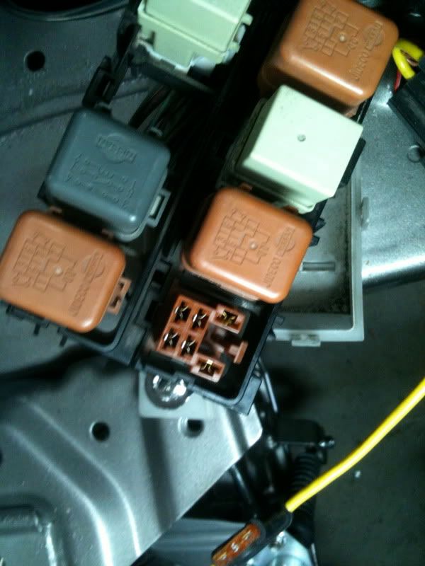
This might be the wire to tap in:
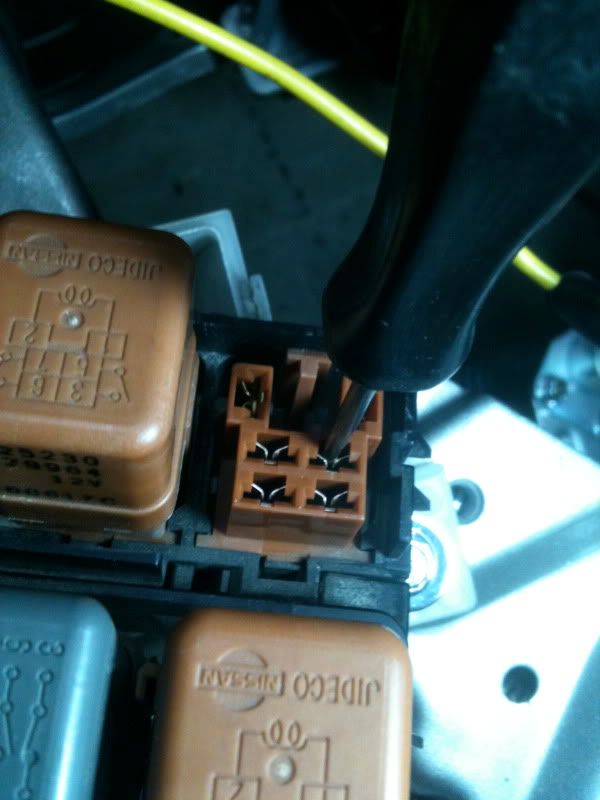
Pics from underneath the relay box:
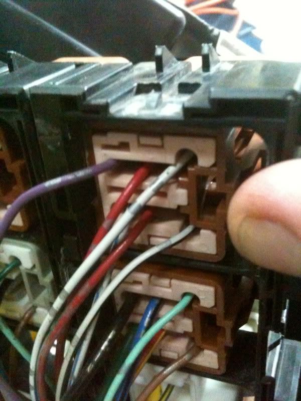
The red wire in the middle of the top row is the one I believe that supply power to the coil.
See the pics:
Connector box with the ECM relay:
This might be the wire to tap in:
Pics from underneath the relay box:
The red wire in the middle of the top row is the one I believe that supply power to the coil.
Last edited by doublea; Jun 24, 2010 at 05:46 AM.
Does this mean that I cut the wire from underneath, leaving a one inch snake on the connector side, then there will be one wire going to the connector and one wire going to the coil. It's been a while since I have purchased the amp so I dont remember how many wire there is to hook up.
I will try to make a schematic so it will be easier to understand.
Yup - I did this - maybe 2 years ago - to get enough spark for my sprayed 3.0. It's pretty simple to install - there is one common feed wire for all the coils going through one of the connectors up by the battery. It's listed in the FSM.
The power supply has some connectors for IN and OUT - cut off the connectors to get to bare wires. There is one pair for IN and one pair for OUT. Connect the ground wires together and connect to the battery (-) terminal. Once you locate the red wire going into the connector for coil power, snip it and connect the power supply IN (+) wire to the harness side and connect the OUT (+) wire to the connector. Set the slide switch to 15 volts initially, and your car will start right up, if you get it right.
Be sure and protect the power supply from rain water. I mounted mine in front of the battery, where it's easy to change.
Need more spark? Set the output to 16 volts. This power supply will go much higher, but your coils might not like 22 volts.
That should be it
I left the ohm meter at the office yesterday, crap... I wont have the chance to take care of this until until next week, I'm taking a few days off with family & friends at our country house to celebrate " La St-Jean Baptiste " wich is the equivalent of the 4th of july for us in Quebec. I will come back tuesday and take 2 full days to work on the car, at this point I'm only missing the radiator hoses and the 2 hoses the that goes from the tranny to the rad. yesterday I received the hose kit for the rack & pignion and power steering. During those 2 days I want to install the remaining parts but also fabricate the alternator bracket, battery box support and for most finish the black box installation.
Yesterday I ordered a new black box since the one I have was repaired but I wasn't sure if it was sealed correctly so I dont want to take a chance. I know I'm getting close
and I should be able to start it in july, this is my ultimate goal and I will work my bott's off to meet that dead line and make her run again. I'm sure if I had the help of 2 guys that know there stuff we would be able to start her in a matter of a day or two but my friends are not mecanically incline so this is not an option.
Can you do me a favor? Can you measure the bottom rad hose?
I need to see how long the 5th gen hose is from the entrance of rad to the first bend going up.
My turbo pipes hit the hose and if the 5th gen hose is a lil bit longer that will be perfect for me.
I need to see how long the 5th gen hose is from the entrance of rad to the first bend going up.
My turbo pipes hit the hose and if the 5th gen hose is a lil bit longer that will be perfect for me.
Do you happend to have a modified thermostat housing ?
Hi Kevlo, from the bottom strait to the top it is 10 inches, there is another 3-4 inches to reach the regular thermostat housing location. I will double check my measurement this morning and will report back if any change.
I'm going to buy the radiator hoses shown here: http://www.coolflex.com/cfm/welcome.cfm
I'm going to buy the radiator hoses shown here: http://www.coolflex.com/cfm/welcome.cfm
Last edited by doublea; Jun 30, 2010 at 06:26 AM.

http://www.summitracing.com/search/D...s/?Ns=Rank|Asc
Should save you some money, they all look pretty much the same to me.
We just need to measure the inner id. Def looks less than 2in.
Should save you some money, they all look pretty much the same to me.
We just need to measure the inner id. Def looks less than 2in.
So basically we would need 2 of this: http://www.summitracing.com/parts/SU...n%7cUpper+hose
http://www.summitracing.com/parts/SUM-390048/
Or that and use it for both.
http://www.summitracing.com/parts/SPE-7789/
Or two of those
I will get them eventually. Need to sell some things first.
Or that and use it for both.
http://www.summitracing.com/parts/SPE-7789/
Or two of those
I will get them eventually. Need to sell some things first.
I think the 48" kit only come with 2 adaptors but we need 4 right ?
I forgot to ask, do you happend to know what is the tranmission cooler kit that people buy for their supercharged 2k1 max ?
Thanks for your input I really appreciate your help.
Thanks for your input I really appreciate your help.
You want a large cooler, and since your are up north; you need a cooler that has a cold fluid bypass.
http://www.bulkpart.com/Merchant2/me...roduct_Count=3
Lol that might an overkill but I think streetz is using something similar.
But here is a bypass:
http://www.bulkpart.com/Merchant2/me...roduct_Count=7
And here is a decent sized cooler:
http://www.bulkpart.com/Merchant2/me...roduct_Count=2
http://www.bulkpart.com/Merchant2/me...roduct_Count=3
Lol that might an overkill but I think streetz is using something similar.
But here is a bypass:
http://www.bulkpart.com/Merchant2/me...roduct_Count=7
And here is a decent sized cooler:
http://www.bulkpart.com/Merchant2/me...roduct_Count=2

I went with the largest cooling capacity one available at my local AutoZone. It's meant for things like RV's and full size trucks for towing. It's a bar and plate style and approximately 14"x12"x1". It came with all the necessary hardware and more than enough transmission line for the installation. Granted I'm using it on my '95, and you asked about 2k1 supercharged max's, but the sampe principles apply - more surface area and cooling capacity at high efficiency is all that really matters.
edit: The cooler Kev posted at the end of his post is basically the one I have.
edit: The cooler Kev posted at the end of his post is basically the one I have.
Last edited by Mad-MAX_SE; Jul 1, 2010 at 07:24 AM.
I went with the largest cooling capacity one available at my local AutoZone. It's meant for things like RV's and full size trucks for towing. It's a bar and plate style and approximately 14"x12"x3/4". It came with all the necessary hardware and more than enough transmission line for the installation. Granted I'm using it on my '95, and you asked about 2k1 supercharged max's, but the sampe principles apply - more surface area and cooling capacity at high efficiency is all that really matters.
Last edited by doublea; Jul 1, 2010 at 07:35 AM.
Ok I see, but we dont have Autozone in Canada, so I was thinking to order from Summit Racing.
Here is what I'm thinking to order:
http://www.summitracing.com/parts/FLX-3953/
http://www.summitracing.com/parts/FLX-45201/
What do you think ?
Here is what I'm thinking to order:
http://www.summitracing.com/parts/FLX-3953/
http://www.summitracing.com/parts/FLX-45201/
What do you think ?
You want a large cooler, and since your are up north; you need a cooler that has a cold fluid bypass.
http://www.bulkpart.com/Merchant2/me...roduct_Count=3
Lol that might an overkill but I think streetz is using something similar.
But here is a bypass:
http://www.bulkpart.com/Merchant2/me...roduct_Count=7
And here is a decent sized cooler:
http://www.bulkpart.com/Merchant2/me...roduct_Count=2
http://www.bulkpart.com/Merchant2/me...roduct_Count=3
Lol that might an overkill but I think streetz is using something similar.
But here is a bypass:
http://www.bulkpart.com/Merchant2/me...roduct_Count=7
And here is a decent sized cooler:
http://www.bulkpart.com/Merchant2/me...roduct_Count=2
My car wont be driven in cold weather anymore so I guess I dont need a by pass valve ?