My n/a project


I'm wondering if it would start without the black canister hoses connection not completed ? this is related to the emission system if I'm not mistaking right ? it would probably trigger a bunch of CEL. I'm going to order the radiator hoses over the week-end, I also need to buy a radiator overflow tank, new belt, a blow by tank. I need to fix one of the line on the ABS actuator that leak, it's an easy fix though. The battery relocation bracket for the Box need to be finish and be fix in the trunk, the battery cable is pass thru the trunk and just need to be cut at the right length. I might connect just one exhaust line when the time come to crank her up, I need to figure out the second muffler pipping but I have everything beside the tig welder ( which I'm shopping for )
I have a good amount of left over bracket that I need to figure out where they go, I might post some pics and see if anyone can help in that aspect. I am slowly getting there but summer will be over in 4-5 weeks here so I'm going to spend more time as the fall approach.
I have a good amount of left over bracket that I need to figure out where they go, I might post some pics and see if anyone can help in that aspect. I am slowly getting there but summer will be over in 4-5 weeks here so I'm going to spend more time as the fall approach.
The car will start w/o any of the evap stuff and the cels you can just reset later on.
97_Roadrunner
Merci pour les bon mots. Thanks for the good words, project is coming alone and now that summer is slowly fading I'll spend more time in the garage than in the boat or seadoo. Lol
Kevlo
I didn't know that so as soon as the essential is done I'm going to crank that biatch.
Tomorrow I will be spending the evening working on the car like ( 6pm - 1 am ) wife will be at the town house with the kid. Stay tune D day is approaching.
Yea, as long as you plug the holes on the IM so it doesn't have a vac leak, it should turn on.
You need spark, fuel, cam/crank sensors, maf, tps, and park/neutral swtich to turn the car on IIRC, maybe a few more things that I can't think of. But the EGR/Evap is NOT on that list
You need spark, fuel, cam/crank sensors, maf, tps, and park/neutral swtich to turn the car on IIRC, maybe a few more things that I can't think of. But the EGR/Evap is NOT on that list
IM hole has been fixed with epoxy so I shouldn't be a problem. As for spark, fuel, cam/crank sensors, maf, tps, and park/neutral switch it's all done unless one is defective but I will know soon enough. One thing though is the belt I need to get new belt, so I'm wondering what are the size ( I can check in the FSM ) but if anyone knows that feel free to chim in.
Belt size as per my measurement 34.5 or 35 inche for the serpentine belt since I'm not putting back the A/C compressor at least not now. The P/S belt, luckily I had 2 brand new one. I tried to install the P/S one but even though the P/S tensioner was completely loose, I couldn't put the belt in so I'm thinking maybe, I have to remove the screw completely ? I checked in the fsm but didn't learn anything new. I'm going give it another try. One thing that bother me, is the vacuum nipple for the brake booster on the I/M is focked up so I'm thinking can I use the 1/2 " pipe on the mid pipe ? I would simply put an adaptor. The 1/2" tube on the mid pipe is no longer needed since I'm putting a blow by can. That's it for now I'm going back and work another hour or two.
For the one that it may interest, the 6 ribs serpentine belt to use without the A/C compressor is 34.5 " length ( this is for a 2k1 maxima ) this is with my custom alternator bracket. I ordered a 35" 6 ribs belt from a local car part store and will get it tomorrow.
At this point I'm only missing the radiator hoses, blow by tank, a radiator over flow tank
and fix the broken nipple on the UIM > this is for the brake booster. I also need to fix 2 of the brake line that connect to the ABS actuator, I also need to put all the fluid in the engine but that should only take 15-30 minutes to do. Frankly I hope to be able to finish this within the next week and try to start the engine.
I think 15inches? But I dunno if that includes the bends or if it is just the overall distance port to port
http://www.rockauto.com/catalog/x,ca...,parttype,2058
http://www.rockauto.com/catalog/x,ca...,parttype,2058
Ok thanks. I finally ordered the Radiator Hoses, I bought the hoses from this site: http://www.coolflex.com/cfm/welcome.cfm
The hoses are a little bit more expensive but they have the exact size for our car
( inlet /outlet of 1 3/8" ) and are made in US. I'd rather buy stuff that is made in US or Canada, that is the best way we can protect our economy and our jobs. I should get the hose by next week and will post pics once I get them.
Thanks
AA
Thanks for your kind support. We will have to get together one day or another, ( food, beer and the whole nine yard ) I'm going to bring the car in the US next year, hopefully Maxus 2011 and possibly other.
Yea, definitely. I would love to check out the car. I guess you can check out my turbo 4th gen but it won't nearly be as nice as your car haha.
Oh, what have you done to the interior? I recently put in some custom 350Z seats which are MUCH comfier than the stock seats.
Yea, definitely. I would love to check out the car. I guess you can check out my turbo 4th gen but it won't nearly be as nice as your car haha.
Oh ya I've seen your 4th gen, it's a nice car but your faster. lol
Oh, what have you done to the interior? I recently put in some custom 350Z seats which are MUCH comfier than the stock seats.
Oh ya I've seen your 4th gen, it's a nice car but your faster. lol
Oh, what have you done to the interior? I recently put in some custom 350Z seats which are MUCH comfier than the stock seats.
That's a good idea to put the Z-seat, they must be expensive though, I'll check tonight.
BTW I was unable to put the 34.5" 6 ribs belt in, so I went to get a 35" and now the tensioner is at the max and the belt is tight but not super tight, I might have to adjust the Alt bracket a little.
I haven't done anything to the interior, but I will eventually. I want to finish the exterior so to speak and once the car is running fine, I will overhaul the interior, but before this take place I still have a lot to do, as I want to paint the car this winter so it's ready for spring 2011.
That's a good idea to put the Z-seat, they must be expensive though, I'll check tonight.
That's a good idea to put the Z-seat, they must be expensive though, I'll check tonight.
There is my interior overhaul. I need to update it with better pics of the seats.
As for the ps belt, ya if you can adjust the bracket, you don't want it to squeal or anything
My bad the belt is fine, I though that the tensioner was at the max but it wasn't, just a little notch in the stud thread so I used a little force and WD40 and everything is just fine and the belt is tight. I also find out why the UIM fix didn't work, the adaptor was not deep enough into the UIM to stick there with the JBweld, I'm going to re-thread the whole and put back the hose coupler in the UIM with JBweld epoxy, that should fix it good.
Last edited by doublea; Aug 22, 2010 at 07:08 AM.
I dunno if you ever hooked up the coil booster, but here:
http://forums.maxima.org/supercharge...ster-pics.html
In my last post I found the wire for the 5th gen
http://forums.maxima.org/supercharge...ster-pics.html
In my last post I found the wire for the 5th gen
Hey guys, special thanks to Kevlo and greymax. Decide to give it another try, took me a while to understand the diagram but I think I got it. I took few pics. The only pics is the one showing the wire that I think need to be tap-in, if my conclusion are right. I'd really like if some one can confirm my assumption.

1- 5th gen Relay box ( or whatever it's called ) showing the location of ECM relay
http://i3.photobucket.com/albums/y89...layBox-ECM.jpg
2- ECM relay connector removed
http://i3.photobucket.com/albums/y89...ectorcover.jpg
3-A close up shot of the ECM with the connector cover removed
http://i3.photobucket.com/albums/y89...verremoved.jpg
4- ECM wires from underneath
http://i3.photobucket.com/albums/y89...underneath.jpg
5-ECM wire # 7, if my understanding of the diagram EC587 / EC588 is correct, this is the wire to tap in.
http://i3.photobucket.com/albums/y89...re7fromECM.jpg
Last edited by doublea; Aug 22, 2010 at 12:03 PM.
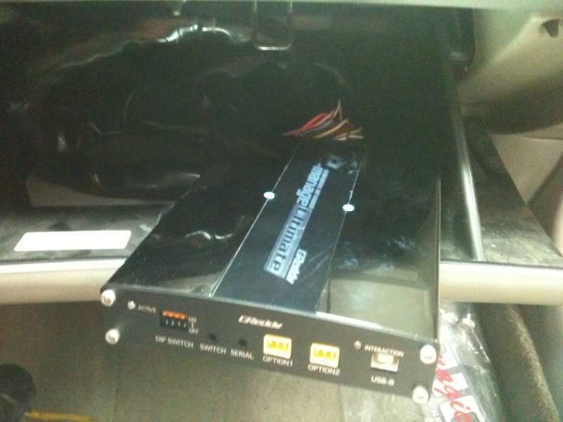
Now here is the pics of the power supply, I can take care of the power source of the P/S, I'm going to pass a wire true the firewall so the P/S reside in the car not in the engine bay. I just cut the power output connector on the P/S and there is 2 wires, 1 red & 1 blue it would make sense that the blue wire is the negative and the red is positive
Now, do I need to connect the negative wire (blue)to the chassis or to the negative on the battery ?
I need someone to confirm that wire # 7 is the right wire to tap-in, secundo I'm not sure how to tap in the wires, let me guess that I have to cut wire #7, so that will leave me with 2 side, the wire that come from the ECM connector and a wire that go to EC48, that go to the coil ( if my memory of the diagram is right )
i confirm, from my understanding of the fsm diagram, i also came to the same conclusion that it is that wire you are indicating, it just seems weird that an ignition source for all 6 coils is on suck a small wire.
Just went thru everything again and I come to the conclusion that the wire # 7 (E32) go to both the condenser F34 and to wire # 3 on each coil. I have checked on the front coil and each of them have the red wire located at the same place so I think we're good to go.
I have looked at greymax wiring diagram, for the most I think I can replicate what he did but I need to be sure of the P/S wiring though. To red wire is generally the positive so the blue has to be negative but I'm wondering if I wire it on the battery negative terminal or on the chassis ? Thanks for your input. It would have been easy to check the signal with a voltmeter but the battery is not hook up yet, as a matter of fact I think my yellow top is done, I have charged it few time over the year but 4 years of inactivity might have kill it.
I have looked at greymax wiring diagram, for the most I think I can replicate what he did but I need to be sure of the P/S wiring though. To red wire is generally the positive so the blue has to be negative but I'm wondering if I wire it on the battery negative terminal or on the chassis ? Thanks for your input. It would have been easy to check the signal with a voltmeter but the battery is not hook up yet, as a matter of fact I think my yellow top is done, I have charged it few time over the year but 4 years of inactivity might have kill it.
I just checked again on greynax thread #1 and in the pics, there is a black connector on the driver side from which he tap-in, I think I found the connector, it is attached slightly underneath the fuse box, I was unable to clearly identify it has, I didn't had my glass, lol
After dinner I'm going to remove the 2 bolts that hold the fuse box and locate the thicker red wire. It's a little complicate but going back and forth and double checking thing make me realize that wire # 7 is in the loop but it's not there that we have to tap in. I'll take some more pics later.
After dinner I'm going to remove the 2 bolts that hold the fuse box and locate the thicker red wire. It's a little complicate but going back and forth and double checking thing make me realize that wire # 7 is in the loop but it's not there that we have to tap in. I'll take some more pics later.
ok, success on a 5th gen, couple tips to make it quicker..... as said negatives together tapped to battery, then your positive input (car charger end) attaches to relay and the output end to the wire coming out of the relay and voila as stated car fired right up.
Nope - I have a 99 Max.... That's the location I tried to explain, based on the 2001 Max FSM, but without a 5th gen around for px ....
Same deal on my '99 - teeny little wire for all six coils - of course, only one is triggered at a time, and only three coils fire per revolution, so really that wire just recharges the magnetic field for one coil at a time.
I found the connector, as you can see on the pics below, it is very similar as to the one show on post #1 in greymax thread.

See the red/blue wire, that's the output on the P/S I'm going to fix it the same as greymax but I'll take a look at your below post ( sorry I'm slow )

See the red/blue wire, that's the output on the P/S I'm going to fix it the same as greymax but I'll take a look at your below post ( sorry I'm slow )
Can you post a pics ?
Last edited by doublea; Aug 22, 2010 at 06:25 PM.
Yesterday I worked until 1:30 am and wired everything so no wire is visible from the engine bay, I have pierce the firewall so I coulf pass thru the 2 wires, I just need to pull the carpet and do the last soldering, I have put the P/S in the center console under the arm rest cover, I have unified the negative and I'm wiring it to the battery in the trunk. Thanks again for helping it is much appreciate.
Sorry for the crappy pics there was not much light.


Sorry for the crappy pics there was not much light.

I'm using connectors only for the P/S, all the remaining wires have been soldered. I dont want to see a connector going off while driving the car.
Edit: I have finally solder all the wire, no connectors. The set-up is completed, i have put the power supply under the arm rest no wire are visible except that I have kept a 4-5 feet of wire loop so it would be more handy to have the power supply in my hand while in front of the car. I'll take some pics later. At this point I only need to hooked up the negative wire to the battery but this is an easy one.
My friend is back from Italy, I have drop him the battery relocation box so he can fabricate a frame, this way the box will be solidly fix on the chassis, better be safe than sorry.
Last edited by doublea; Aug 26, 2010 at 11:56 AM.